for the technician
785
692_R01
69
32.5
35
14
330
52 52 88
13
39 40 30 46.5 52.5
14
35
335
400
32.5
666
23
20
30
712
AA
B B
C
D
A1
B1
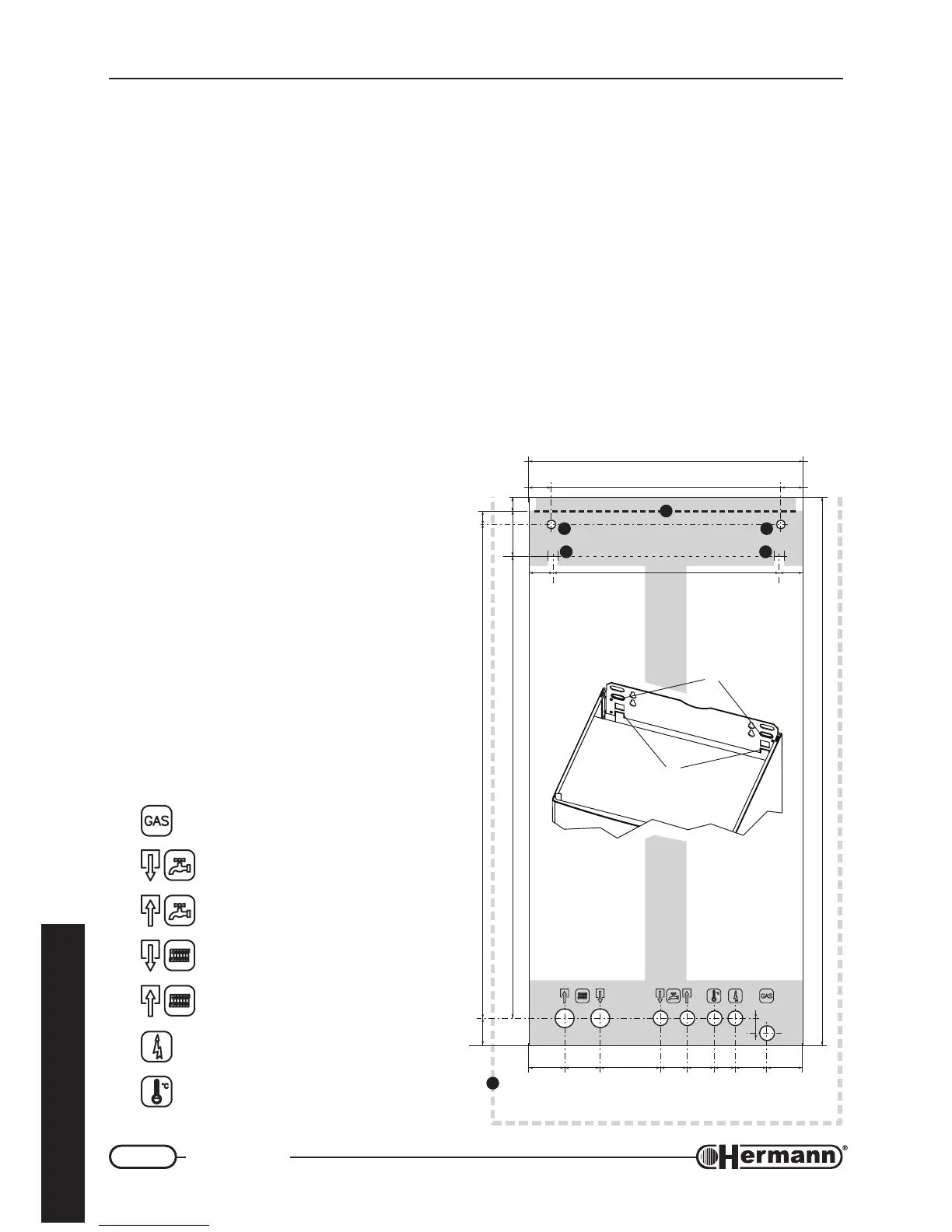
Boiler hanging
REMARK: A re-utilizable metal jig can be ordered separately, so as to facilitate connections and
fixing points positioning (when the standard connection kit is used). If the standard connection
kit is not used, refer to the “Dimensions” drawing (Technical Data section) for the position of the
connections directly on the boiler.
REMARK: If SUPERMICRA replaces a MICRA, see next section “Replacement of a MICRA boiler”
to keep the same hydraulic and flue connections.
— Consider gas boiler size and sufficient clearances [C] for servicing/repair. It is recommended:
50mm on both lateral sides and 300 mm on lower side;
— To fix the boiler with wallplugs (“stud” type with nut), center the relevant wall holes as regards to
[A] points. To hang it with open hooks, place hooks in correspondence with [B] points.
— Using the jig or respecting the measures indicated in the figure, fix up electrical connections
and all ducts for heating flow and return, cold water, hot water and gas.
— Hang the boiler to the wallplugs or hooks,
using the holes ([A1] for the wallplugs and
[B1] for the open hooks).
— Remove the plastic caps from the boiler
connections prior to connecting boiler to
the pipework.
REMARK: To facilitate boiler connection, it is
possible to remove temporarily the lower
grid, unscrewing its four screws.
— As far as air inlet and flue outlet ducts are
concerned (forced draught models),
please refer to “Flue systems” paragraph,
where measures are referred to the upper
edge of boiler’s body [D].
Gas (1/2")
Hot water OUTLET (1/2")
Cold water INLET (1/2")
Heating RETURN (3/4")
Heating FLOW (3/4")
Electrical power supply
Room thermostat