for the technician
Gas valve pressure
regulation (MAX-MIN)
— Loosen (2-3 turns) the screw of pressure tapping point
for gas outlet [1] of the gas valve and insert the
manometer sensor. In the “SE” models unthread from
the “Vent” [3] the silicon tube coming from the sealed
chamber;
— bring and keep the Summer/Winter Selector in the po-
sition Chimneysweeper
for at least 3 seconds, then
let the selector return in the position Summer . The
green lamp flashes rapidly and the burner ignites at
the maximum outlet, not modulated, for a period suffi-
cient to make the checks and the measurements. The
produced heat is carried off by the heating system;
— wait for at least 10 seconds and check that the pres-
sure corresponds to the MAX value indicated in the
“BURNER PRESSURES” table of the specific model;
— extract one of the connectors [4] that supply the modu-
lation coil; verify that the measured pressure corre-
sponds to the MIN value indicated in the “BURNER
PRESSURES” table of the specific model;
— reinsert the connector [4];
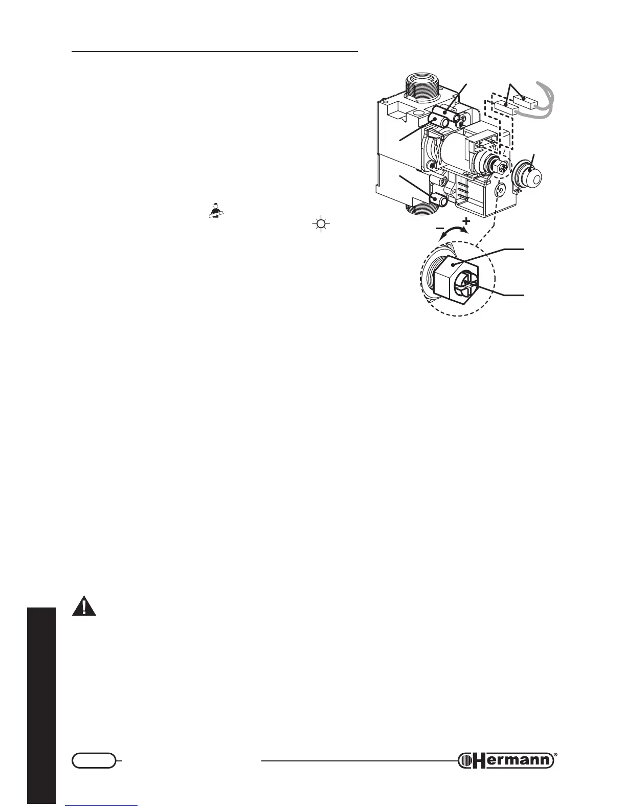
— if it is necessary to adjust the regulation, proceed as it follows, referring to the figure:
• take off the protection cap [C];
• adjust MAX pressure acting on the nut [B] (10 mm). Turn clockwise to increase pressure,
counterclockwise to decrease pressure;
• extract again one of the connectors [4];
• adjust MIN pressure acting on the screw [A] (with a 4 mm screwdriver), paying attention
not to contemporarily move the nut [B]. Turn clockwise to increase pressure,
counterclockwise to decrease pressure;
• reinsert the connector [4] and check that MAX pressure is not changed;
• mount the cap [C];
Important: lock the adjustment device after any setting operation.
— For the “SE” models reinsert the tube in the “Vent” [3] of the gas valve. ATTENTION:after this
operation, the value measured by the manometer could decrease due to pressure compensation.
This fact is normal and does not require any change of the regulation;
— Screw the pressure tapping point screw for gas outlet [1] and verify that there is no gas leak.
— To switch off the burner, turn the Summer/Winter Selector to the “0” position.
GAS VALVE
1 = Pressure tapping point
for gas outlet
2 = Pressure tapping point
for gas inlet
3 = Vent (mod. SE)
1
2
3 4
C
B
A