for the technician
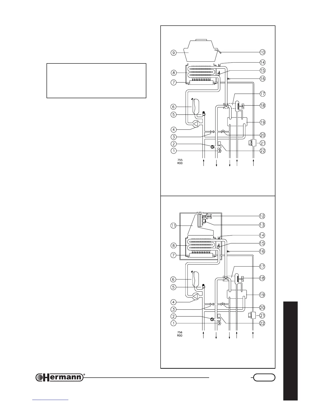
BOILER SCHEMATIC
SUPERMICRA E
SUPERMICRA SE
1 Drain valve
2 Heating thermometer + gauge
3 By-pass
4 Pump
5 Heating system safety valve 3 bar
6 Expansion vessel
7 Burner
8 Primary heat exchanger
9 Flue hood (“E” models)
10 Flue thermostat (“E” models)
11 Flue hood (“SE” models)
12 Flue pressure switch (“SE” models)
13 Fan (“SE” models)
14 Safety thermostat
15 Venting device
16 NTC temperature sensor
17 Hydraulic 3-way valve
18 Priority pressure switch
19 Domestic exchanger
20 Filling valve
21 Gas valve
22 Loss of water switch
DOMESTIC
WATER
GAS
INLET
HEATING
FLOW
OUTLET
RETURN
WARNING: This scheme is made for in-
formation only. To make boiler hydrau-
lic connection either use fixing jig or the
drawing inserted in the section “Instal-
lation” or the “Dimensions” drawing.
DOMESTIC
WATER
GAS
INLET
HEATING
FLOW
OUTLET
RETURN