7
COMPONENTS
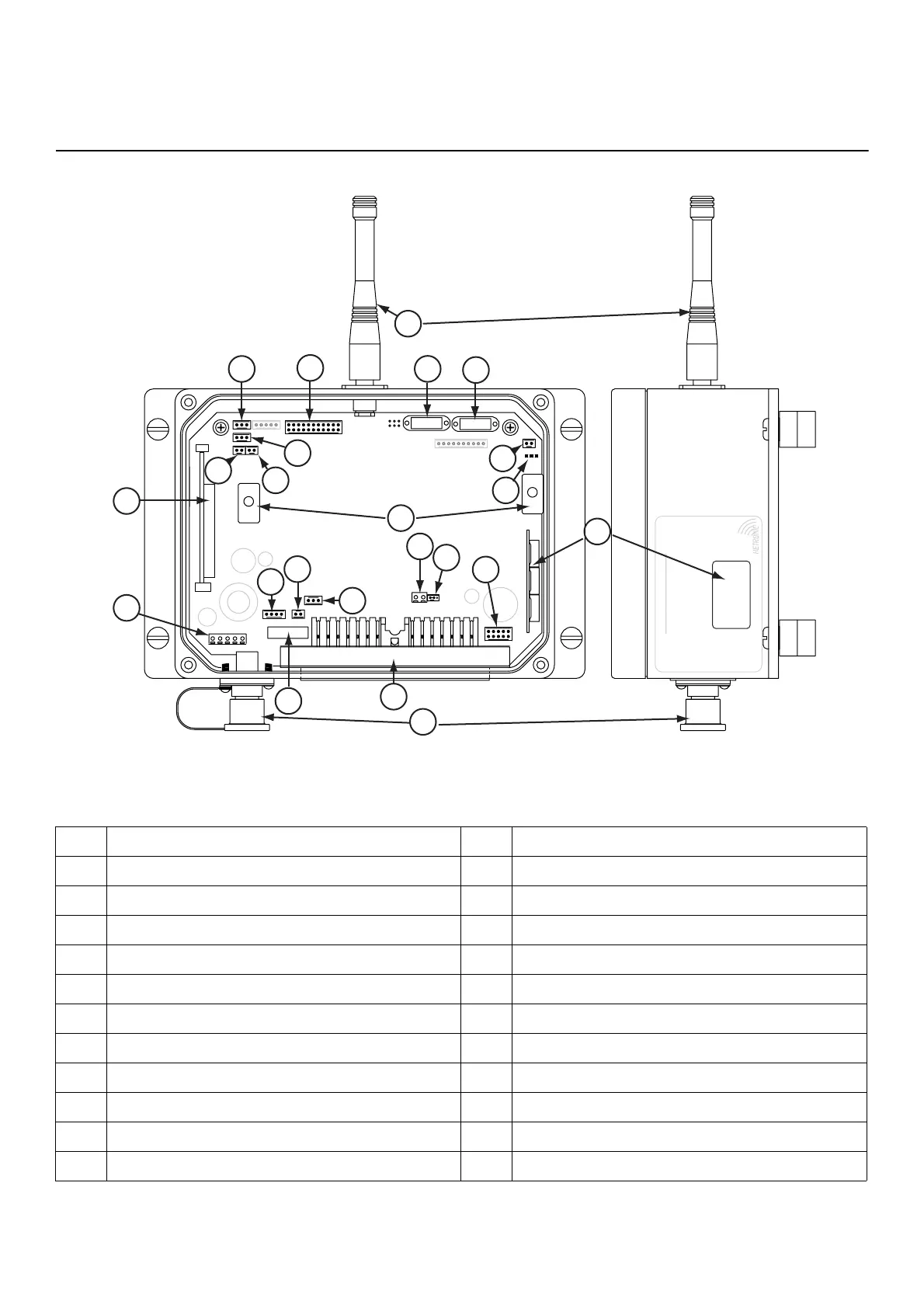
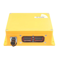
Figure 1: BMS-2 Components (VC)
Table 1: BMS-2 Components (VC)
1 70 Pin Connector (X1) 13 Antenna
2 Fuse (7.5Amp) 14 Address Module (Stop Decoder)
3 External Inputs 15 Address Module (Main Decoder)
4 2-Pin Connector (output) 16 CAN Termination (X2)
5 RS232 Interface 17 CAN Interface (X3)
6 Terminal Block 18 Status Indicator
7 RF Module (A2) 19 Internal Analog Outputs (X8)
8 Green LED (X14) 20 URef Select (Internal/External)
9 Transmitter OFF Connection (X15) 21 Common YO/Stop Output
10 Transmitter Feedback (X13) 22 Mounting Screw Recesses
11 Receiver RF Module Connection (X11) 23 Cable Control/Programming Port (X2)
12 TTL Digital Outputs (X7)
BMS-2: S
stem Status Indicators
x x 0 - Normal
eratio
x x 1 -
ystem Not
tarte
x x
-
mm
ni
i
n Err
x x 2 - Active E-Sto
x x 4 - Passive E-Sto
x x x . - Dot blinks = Tel
ram O
x x . x - Dot on = Pro
ram Mod
x x - Err
r
x x - Analo
Channel 1 activ
x x - Analo
Channel 2 activ
www.
etron
c.co
... up to Analog
hannel 8
1
2
1
2
8
1
2
3
4
5
6
7
9
10
11
12
13
14
15
16
17
18
19
20
21
23
22
X14
X15
X13
X11
X7
X2
X3
X18
X8