10
SYSTEM FEATURES
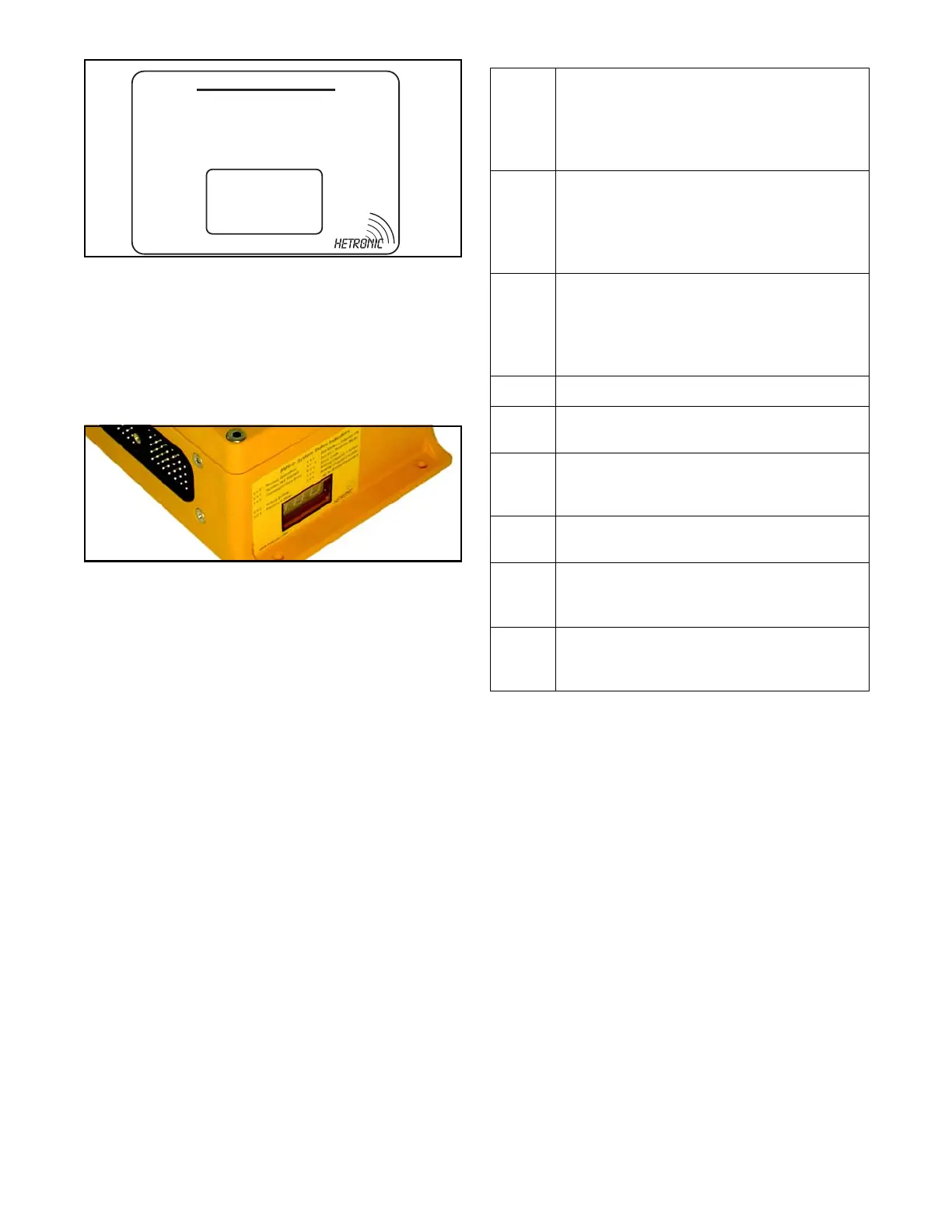
Receiver Display
The receiver has a 3-digit, 7-segment display on the
outside of the housing to show operation status and
Error Codes. The following table shows basic
operational status codes. Error Codes are assigned
per specific customer requirements.
Speed Reduction/Speed Select Function
This radio remote control system is equipped with a
speed control function. It allows speed reduction to
75%, 50%, and 25% of the maximum speed using a
switch on the transmitter. Other speed select options
can be programmed with the BMS-2 software.
Ramp Function
The purpose of the Ramp Function is to allow a gradual
start or stop to a machine movement to help prevent
load or basket swing. The rate of increase and
decrease is set with the BMS-2 software.
Interlocking Functions
This feature prevents contradictory operator
commands from the transmitter. Certain functions can
be enabled or disabled when another function is
activated or inactive. An example is hoist up and hoist
down. Activating both functions would most likely
damage the equipment. Therefore, hoist up is
interlocked with hoist down so that when one is
activated the other can not be.
BMS-2: System Status Indicators
x x 0 - Normal Operation
x x 1 - System Not Started
x x 3 - Communication Error
x x 2 - Active E-Stop
x x 4 - Passive E-Stop
x x x . - Dot blinks = Telgram OK
x x . x - Dot on = Program Mode
E x x - Error Code
1 x x - Analog Channel 1 active
2 x x - Analog Channel 2 active
www.hetronic.com
... up to Analog Channel 8
001
x x 0 Receiving correct signal, no E-Stop, system
started
Example: 0 0 0 means the receiver is getting a
valid control telegram and all joysticks are in
neutral position
x x 1 Receiving correct signal, BMS-2 in E-Stop, no
E-Stop from TX
Example: 0 0 1 means the receiver is getting a
valid control telegram, all joysticks are in neutral
position, with E-Stop condition in receiver
x x 2 Receiving correct signal, BMS-2 in E-Stop,
E-Stop transmission from TX
Example: 0 0 2 means the receiver is getting a
valid E-Stop telegram and the transmitter
E-Stop is engaged
x x 3 RF interference
0 0 4 Not receiving signal, no RF communication, or
TX is turned off
0 0 0 . Flashing dot after third digit, change the status
with each correct received telegram (green
LED)
0 0 . 0 Flashing dot after second digit indicates
programming mode (Quick-Set)
1 x x Analog output 1 (up to 8) activated, joystick not
in neutral position. System will not start if
joystick is not in neutral position.
E x x Error Codes are assigned numbers based on
customer requirements. See Technical
Documentation for specific codes.