6
OPERATION AND WORK AREA SAFETY
The work area must be free from obstacles, debris or
other tripping hazards. Avoid uneven work areas and
any rough terrain. Always be sure of your footing.
Be aware of overhead obstacles that may interfere with
machine operation.
If a belt or strap is provided with your transmitter, use it
at all times.
PROTECTIVE FEATURES
This radio remote control system is equipped with
electronic and mechanical safety features. Processing
of control signals transmitted from other transmitters is
not possible, since transmission coding is unique to
each system.
These safety features help protect the operator, as well
as others within the work area. The machine functions
can be stopped by pushing the emergency stop button
on the transmitter control panel (EMERGENCY STOP).
NOTE: The e-stop command is transmitted within
approximately 0.5 seconds (450 ms) after the switch is
turned to the "OFF" position.
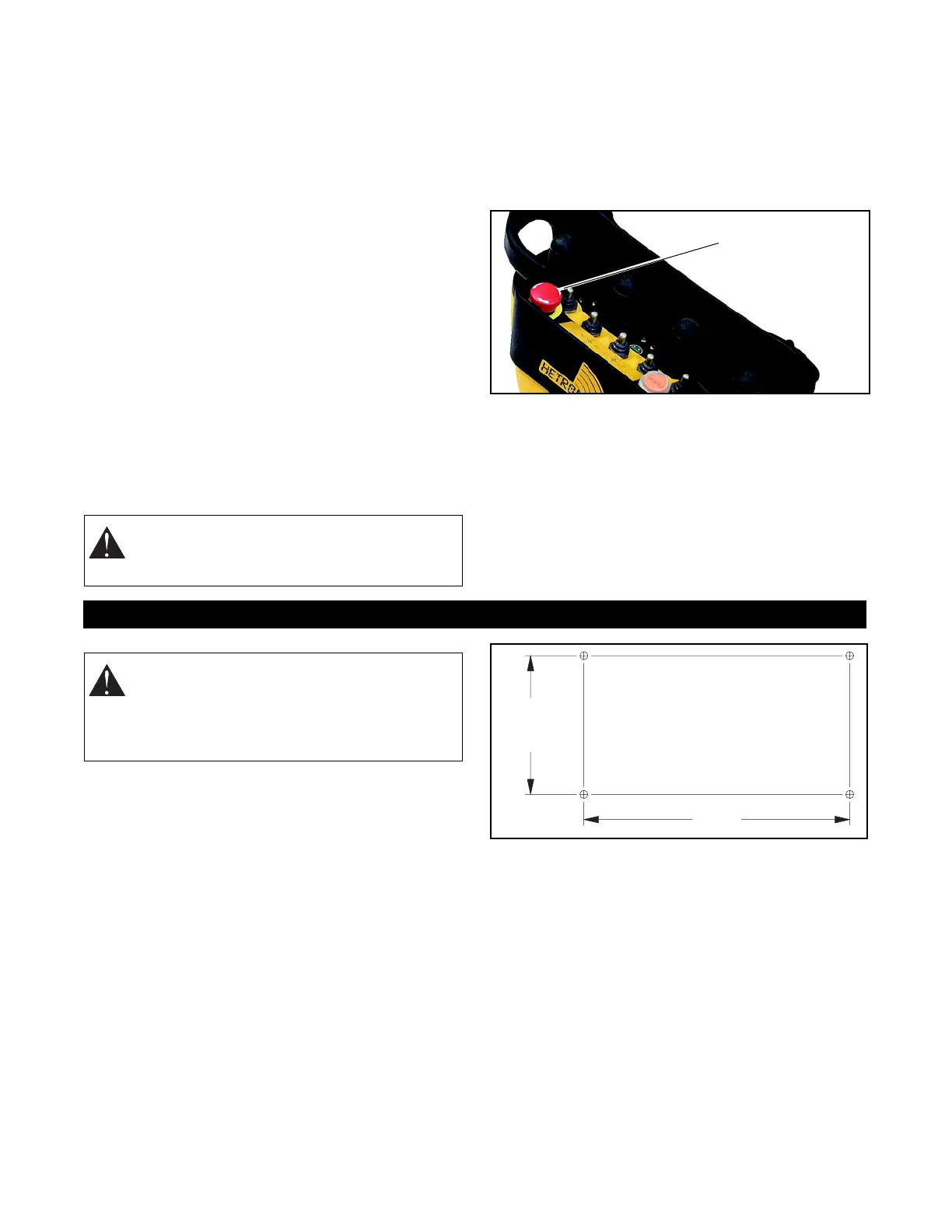
TO STOP IN AN EMERGENCY
1. Press the red "EMERGENCY STOP" pushbutton.
2. Turn the key to "OFF".
3. Wait for all moving machine parts to stop.
4. Refer to machine’s operator manual for further
instructions.
MAINTENANCE
Always shut off power to the machine and the radio
remote control system transmitter and receiver before
any assembly, maintenance or repair.
IMPORTANT: AVOID SYSTEM DAMAGE - ALWAYS
disconnect receiver power supply and control wiring
before welding on any part of the crane/machine.
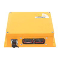
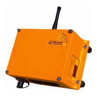
MOUNT THE RECEIVER
Install Receiver and Output Wiring
Select a position for the receiver so that the display is
easily visible, accessible and that provides protection
from violent impact from debris or thrown materials.
The receiver housing is rated IP65 and is protected
against penetration of dust and moisture. Therefore,
weather and elements should not be the primary
concern when installing the receiver.
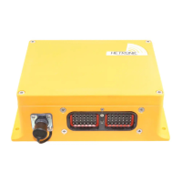
Four mounting holes are required when installing the
receiver unit. The drill pattern and recommended
hardware are shown in the following illustration.
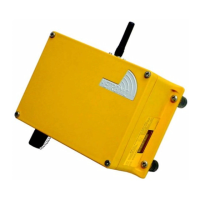
If the receiver includes an attached antenna, mount the
receiver so that the antenna points straight up. The
area around the antenna should be free of
obstructions, especially metal.
WARNING: Accidental start-up can cause
serious injury or death. NEVER remove or
modify any safety feature.
Typical
Pushbutton
Stop
Emergency
INSTALLATION
WARNING: FAILURE TO FOLLOW
INSTRUCTIONS could result in personal
injury and/or damage to equipment. Read and
understand the safety instructions in all
manuals provided.
DRILL PATTERN
Drill 4 holes 9/32" (7mm).
Use 1/4" or 6mm bolts.
4.57"
(116 mm)
9.13"
(232 mm)