7
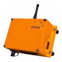
Be sure that the Diagnostic Display panel is clearly
visible.
The receiver wiring is critical for proper system
operation. Make all connections with good quality
contacts or solder joints to ensure proper electrical
contact.
Supply voltage and ground wiring are crucial and must
be connected to reliable connecting circuitry. Do not
use a chassis ground for this equipment. The ground
wire must be connected directly to the vehicle battery
negative post.
IMPORTANT: Power supply wiring must be at least
AWG 12 to prevent power drop.
The output control signals to the proportional control
valves should be routed separately from any wiring that
could produce transient voltage interference.
Interference or "induced voltage spikes" could cause
erratic performance of the proportional controls.
Mount the Actuators (Optional)
Mount and attach the actuators to the hydraulic valves
or to the mechanical linkage with the brackets supplied.
Attach Wiring Harness (Optional)
Plug the wiring harness into the receiver and into the
corresponding actuators.
Connect Electrical Wiring
Connect all remaining wires (power supply, engine
start-stop, etc.) according to the wiring diagram of the
crane/machine and the radio remote control.
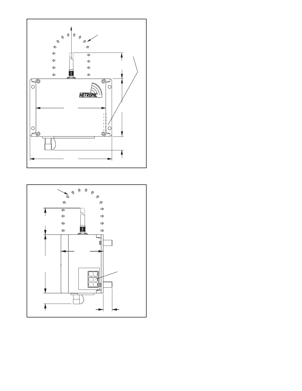
8.29"
(210.5 mm)
9.72"
(246.8 mm)
6.40"
(160.0 mm)
1.00"
(25.0 mm)
4.25"
(106.3 mm)
Antenna must
be vertical
(pointing up).
Area must be
free of
obstructions
Diagnostic
Display Panel
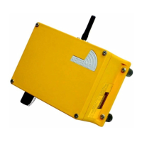
4.25"
(106.3 mm)
6.38"
(162 mm)
4.47"
(113.5 mm)
1.00"
(25.0 mm)
1.00"
(25.0 mm)
Area must
be free of
obstructions
Do not block
visibility of
diagnostic
panel.