Do you have a question about the HGST Ultrastar 7K2 and is the answer not in the manual?
HGST Ultrastar Capacity Enterprise hard drives offer up to 10 TB capacities and are available with SATA interface.
Lists key features of the HGST Ultrastar drives including SATA, TLER, RAFF, PMR, IntelliSeek, NCQ, PWL, MicroFemto Slider, SCT, and WWN.
Enhances drive's ability to prevent data loss through thermal management, environmental protection, and error detection/repair.
Utilizes stored spindle energy to back up HDD cache to on-board flash upon power loss to prevent data loss.
Allows swapping a failed hard drive without powering down the system, enhancing data availability and serviceability.
Provides an activity LED output that is ON during command execution and OFF otherwise.
Bearing design using lubricant layer instead of ball bearings for increased shock resistance, speed control, and acoustics.
Allows system to control drive spin-up immediately or wait until interface is ready.
Unique, multi-generation caching algorithm that evaluates data read/write patterns to optimize performance.
Supports 48-bit and 28-bit LBA and CHS-based addressing for high capacity disk integration.
Supports ATA and SATA power management commands to reduce drive power consumption.
Enables drive's internal status monitoring via diagnostic commands to predict degradation or fault conditions.
Supports ATA Security Mode feature set to create a device lock password for unauthorized access.
Prevents possible electronic failures from corrupting data on the hard drive.
Details performance metrics of the drives, including seek times, latency, rotational speed, and data transfer rates.
Explains the unique, multi-generation disk caching system that incorporates read and write cache for performance optimization.
Improves write performance by reducing delays and automatically relocating defective sectors during write operations.
Implements a multiple segment read cache to maximize cached data, increasing the likelihood of cache hits.
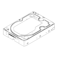
Provides physical dimensions in both English and Metric units for the drive.
Details recommendations for rigidly supporting the drive, screw types, torque, and penetration limits for mounting.
Specifies that the system must be turned off and unplugged if it does not support hot plugging.
Describes how to mount the drive in X, Y, or Z axis for best results, recommending grounding to the chassis.
Advises on using 6-32 screws, recommended torque, and cautions about screw penetration length.
Explains that PCBA and HDA grounds are connected, and mounting screws provide additional grounding.
Lists mean current and power dissipation for various operating modes like Spinup, Read, Write, and Idle.
Details power savings modes (Idle_A, Idle_B, Idle_C, Standby Y, Standby_Z) with their respective current and power consumption.
Explains how SATA APM commands can lower drive power consumption by issuing commands like Standby Immediate.
Describes T13 Extended Power Conditions like Idle_A, Idle_B, Idle_C, Standby_Y, Standby_Z for reduced power consumption.
Specifies the input voltage requirements for the drive as +5.0V ± 5% and +12.0V ± 10%.
Lists ripple requirements for +12VDC and +5VDC power inputs.
Provides information on SATA data connectors, pin definitions, and cabling requirements for Serial ATA.
Details shock and vibration specifications for operating and non-operating conditions, including packaged products.
Specifies operating and non-operating temperature and humidity limits, including thermal and humidity gradients.
Explains where drive component temperatures are measured and the limits to maintain MTBF rating.
Recommends airflow from fans for forced air cooling, as indicated in Figure 3.
Lists operating and non-operating altitude ranges for atmospheric pressure.
Provides typical sound power levels for Idle and Seek modes.
States compliance with RoHS Directive 2011/65/EU for restricting hazardous substances.
Provides a summary specification of the model number suffix for the product platform.
Details SATA 6 Gb/s interface features including NCQ, Staggered Spin-up, ASR, Enclosure Services, Backplane Interconnect, and Auto-activate DMA.
Prevents RAID array dropouts by limiting error recovery time and issuing error messages to the RAID controller.
Helps overcome rotational vibration effects by generating additional control effort to keep the drive head within safe operating region.
Uses linear accelerometers to sense rotational vibration and generate a Differential Sensor Signal (DSS).
Digitizes DSS to a microprocessor for control effort signal generation, supplementing conventional servo control.
Intelligently applies RAFF selectively and adapts to drive parameters for optimal performance.
Aligns data bit magnetization vertically to the disk for increased density and stability.
Calculates optimum seek speeds to reduce actuator movement, saving power, noise, and vibration.
Improves random I/O performance by reordering read commands for faster sequential access.
Protects recording media from wear by initiating forced seeks to maintain lubricant distribution.
Incorporates next-gen femto slider for read/write heads, enabling quicker track-to-track movement and enhanced stability.
Provides a method for hosts to send commands and data to devices using log pages.
Allows host to erase media or write a pattern repeatedly across the media with minimal data transfer.
Allows host to access drive temperature information, reporting it within ±3°C of base casting temperature.
Defines a format for serial numbers, a modification of IEEE extended unique identifier 64 bit standard.
Uses stored spindle energy to back up HDD cache to on-board flash upon power loss, minimizing data loss.
Enables swapping drives without powering down the system, critical for enterprise applications.
Provides an activity LED output that is ON during command execution and OFF otherwise.
Bearing design using lubricant instead of ball bearings for increased shock resistance, speed control, and acoustics.
Details Staggered Spinup for power-up sequencing and Activity Indication for status.
Sequences hard drive initialization to minimize load during power-up.
Provides a low-voltage signal for activity indication, requiring an external buffer to drive an LED.
Allows devices with capacities up to 281 tera sectors or 144 peta bytes, increasing sector count to 16 bits.
Monitors drive's internal status via diagnostic commands, tracking metrics like error rates and power-on hours.
Allows setting master and user passwords to prevent unauthorized access, even if the drive is removed.
Explains setting master and user passwords for device lock functionality.
Defines High and Maximum security levels, impacting data access if the user password is forgotten.
Prevents possible electronic failures from corrupting data as it moves from the interface to the media.
Describes the 8-pin jumper block for factory use only, not enabling features or affecting performance.
Discusses factors affecting reliability, including temperature, cooling, and SMART technology.
States assumptions for error rates, including DC power, FORMAT UNIT command, and exclusion of media defects.
Specifies error rates based on ECC, automatic retries, and reallocation of drive flaws.
Defines a seek error as head positioning failure and describes automatic error recovery procedures.
Defines recoverable, unrecoverable, and mis-corrected read errors, and requirements for measuring them.
Defines interface errors detected by the drive receiver, including running disparity, illegal code, and CRC errors.
Evaluates drive performance under EMI conditions, considering unrecoverable conditions.
Details features enhancing reliability, including Data Lifeguard, Thermal Management, Environmental Protection, and Defect Management.
Enhances data protection with features for thermal management, environmental protection, and error detection/repair.
Details mechanical design, closed loop servo management, and ducted airflow for thermal management.
Protects the drive's internal environment from contamination using filtration and directed airflow.
Explains factory testing and mapping of defective sectors, including sector slipping and grown defect relocation.
Describes how sectors are marked for repair and tested during subsequent write operations.
Explains how unrecoverable errors are marked and handled during offline scans and subsequent writes.
Automatically maps out defective sectors during read/write operations by finding and using a spare sector.
Details the five error recovery methods: ECC On-the-Fly, Read/Write Retry, and Extended Read Retry.
Covers host interface commands including ATA-7/ATA-8, SATA, and Obsolete commands.
Lists the hexadecimal opcodes for ATA-7/ATA-8 commands supported by the drives.
Lists hexadecimal codes for SATA commands, referencing the SATA specification for details.
Lists hexadecimal codes for obsolete commands supported by the drives.
Provides capabilities not covered by ATA/ATAPI-7, reporting completion via SCT status.
Returns a sector of data containing the drive's S.M.A.R.T. data structure and attribute definitions.
Lists supported S.M.A.R.T. attributes with their ID numbers and Pre-Failure/Advisory status.
Details various logs readable via the S.M.A.R.T. Read Log Sector sub-command and their definitions.
Provides precautions for unpacking and handling drives to avoid ESD, mechanical shock, and to keep them in antistatic bags.
Details precautions for handling drives to avoid ESD, mechanical shock, and to keep them in antistatic bags.
Instructs to examine shipping containers for damage and notify carriers or representatives if damage is found.
Details precautions for removing the drive from its container, emphasizing handling by sides and avoiding drops.
Provides steps for removing the drive from its static shielding bag, stressing grounding and avoiding circuit board contact.
Advises turning off power to unload heads before moving the system to protect media and heads.
Explains system power requirements for installation, SATA cable connection, and keyed connectors.
Details blind-mate tolerances for connector pins in X, Y, and Z axes and references figures for pin dimensions.
| Model | Ultrastar 7K2 |
|---|---|
| Category | Storage |
| Form Factor | 3.5 inch |
| Capacity | 1TB, 2TB, 3TB, 4TB |
| Interface | SATA 6 Gb/s |
| RPM | 7200 |
| Cache | 64MB |
| Average Latency | 4.16 ms |
| MTBF | 2 million hours |
| Non-Operating Temperature | -40°C to 70°C |
| Shock Resistance (Operating) | 70 G |
| Shock Resistance (Non-Operating) | 300 G |
| Warranty | 5 years |