August 2005 Page 6 of 23
2005 © HID Corporation. All rights reserved.
VertX V2000 (CS) Quick Installation Guide
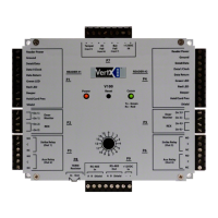
Pin # P7
1 +12VDC
2 Ground
3 Bat Fail -
4 Bat Fail +
5 AC Fail -
6 AC Fail +
7 Tamper -
8 Tamper +
2.2 Wiring VertX
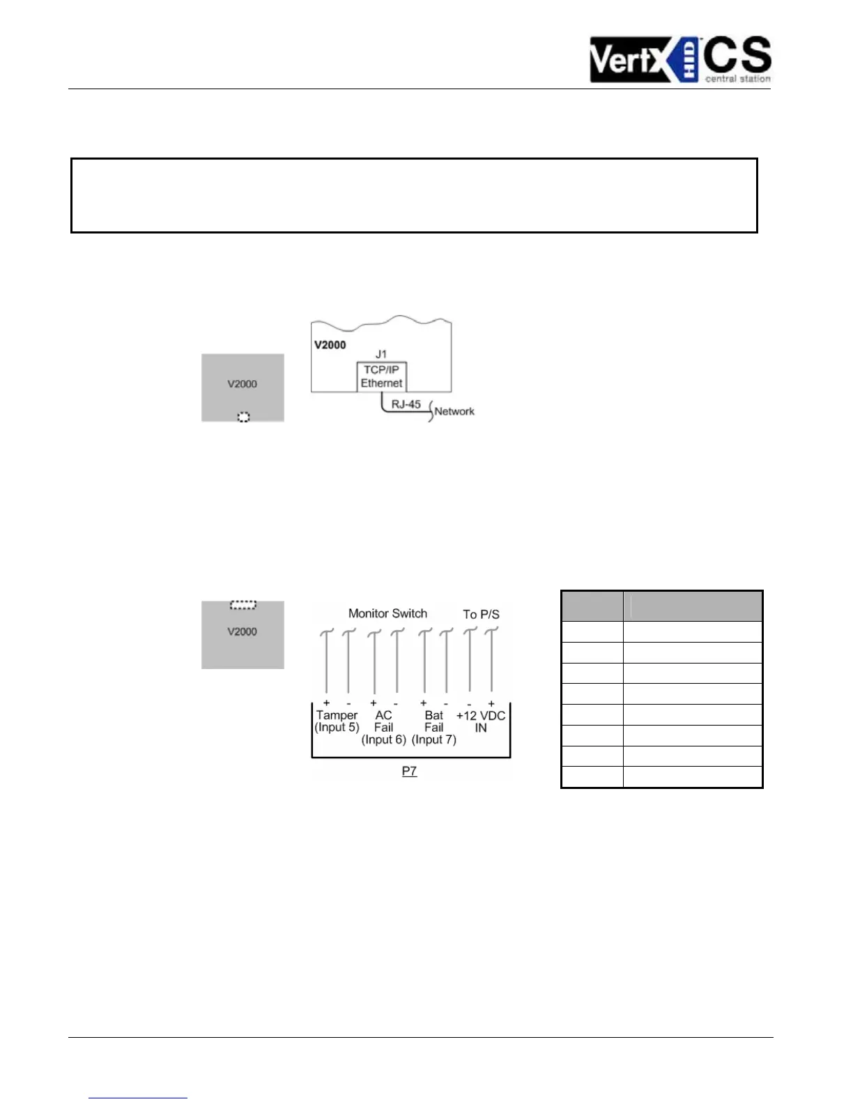
1. Network Connection: Connect the V2000 to the network using a standard Cat5 network
patch cable. Connect one end of the Cat 5 network patch cable to the J1 (RJ-45) connector
on the V2000 and the other end to the network connection point (network jack, hub, switch, or
router) on your site.
2. Power and Alarm input connections: Connect power by providing 12VDC to the P7
connector. +12VDC goes to Pin 1 and Ground on Pin 2. The Bat Fail, AC Fail, and Tamper
switch inputs are wired as shown in the table. Connect the Bat Fail and AC Fail inputs to
battery low/failure and AC failure contacts provided on the power supply. Connect the Tamper
input to a tamper switch on the enclosure.
CAUTION: Connectors on the V2000 sides are positioned to be mirror images and are not
interchangeable once the installation is complete. Therefore, you cannot unplug the connector from
one side of the board and plug it into the corresponding connector on the other side of the board.