August 2005 Page 7 of 23
2005 © HID Corporation. All rights reserved.
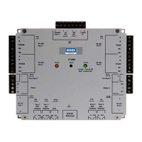
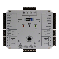
VertX V2000 (CS) Quick Installation Guide
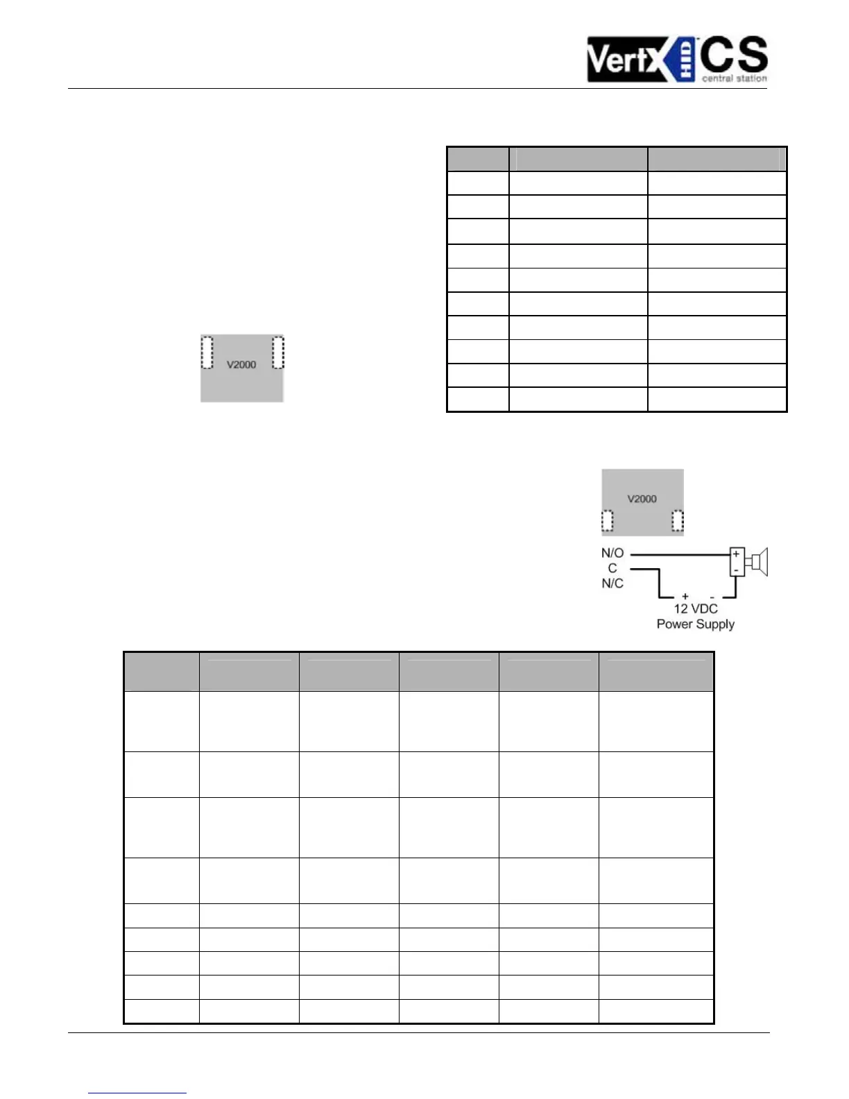
Pin # V2000 P1 V2000 P4
1 Reader Power Shield Ground
2 Ground Hold
3
Data 0 / Data Beeper
4 Data 1 / Clock Red LED
5 Data Return Green LED
6 Green LED Data Return
7 Red LED Data 1 / Clock
8 Beeper Data 0 / Data
9 Hold Ground
10 Shield Ground Reader Power
3. Reader Connections: Connect
Wiegand or clock-and-data interfaces
using the connection table shown. You
can connect up to 10 signal lines for
the reader. Use as many signal lines
as are required for your reader
interface.
Note: Connect the data return line to
the same ground as the reader power,
if the reader is not powered by the
VertX controller’s 12VDC.
4. Output Connections – All Output connections are used for
general purpose controls. The following table shows where the
various outputs are located among the various VertX types. Pin
numbers shown use the convention “NO/C/NC”. For example,
Output 1, V2000: P3 Pin1 is NO (Normally Open) and Pin 2 is
C (Common) and Pin 3 is NC (Normally Closed).
Note: Relay contacts are rated for 2Amps @ 30VDC.
Output
number
V2000 V1000 V100 V200 V300
1
P3 Pins 1/2/3
Strike (lock)
Relay 1
P14 Pins 2/3/4
P3 Pins 1/2/3
Strike (lock)
Relay 1
P3 Pins 2/3/4 P1 Pins 1/2/3
2
P3 Pins 4/5/6
Aux Relay 1
P11 Pins 6/5/4
P3 Pins 4/5/6
Aux Relay 1
P6 Pins 3/2/1 P1 Pins 4/5/6
3
P6 Pins 6/5/4
Strike (lock)
Relay 2
P6 Pins 6/5/4
Strike (lock)
Relay 2
P1 Pins 7/8/9
4
P6 Pins 3/2/1
Aux Relay 2
P6 Pins 3/2/1
Aux Relay 2
P2 Pins 1/2/3
5
P2 Pins 4/5/6
6
P2 Pins 7/8/9
7
P4 Pins 9/8/7
8
P4 Pins 6/5/4
9
P4 Pins 3/2/1