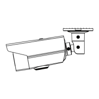
Figure 2. 8 3-axis Adjustment
Installation of Type III Camera
Steps:
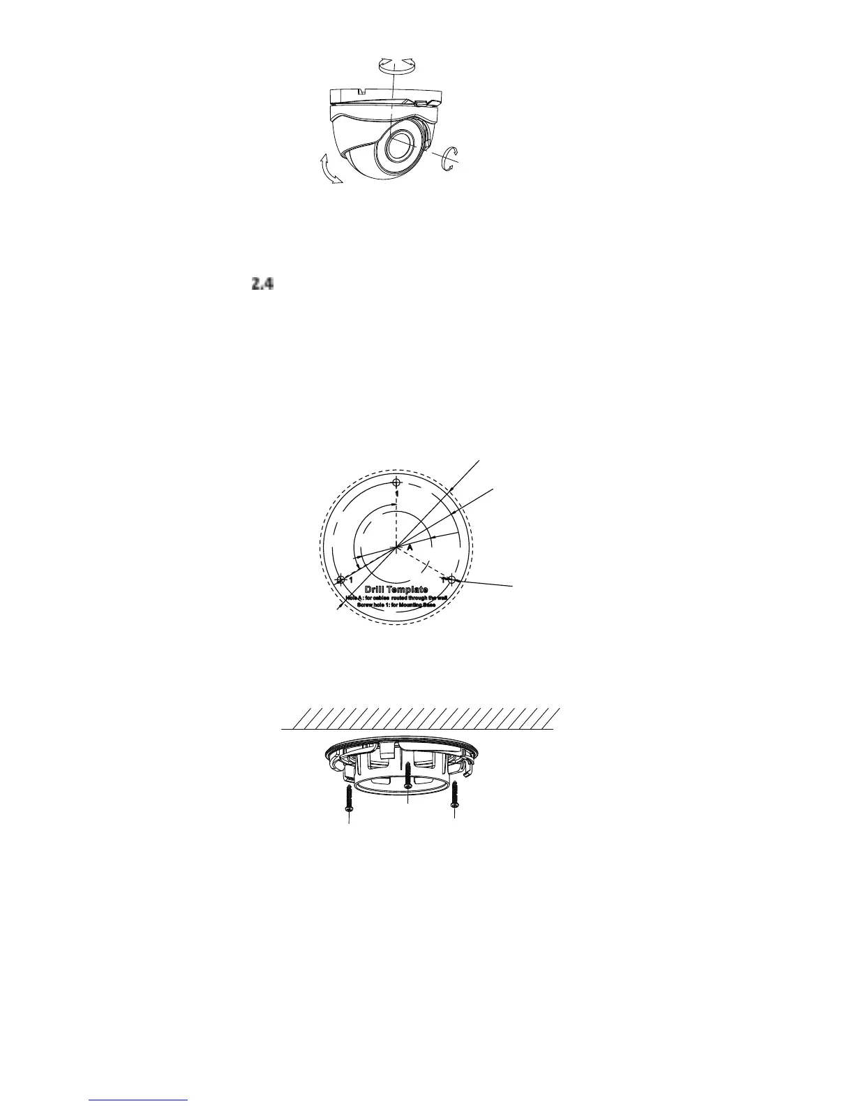
1. Attah the dill teplate supplied to the plae
hee ou at to istall the aea, ad the dill
the se holes ad the ale hole optioal
aodig to the dill teplate o the eilig.
Note:
Cale hole is euied he adoptig eilig outlet to
oute the ale.
Figure 2. 9 Drill Template
2. Attah the outig ase to the eilig ad seue
the ith supplied ses
Figure 2. 10 Attach the Mounting Base to the Ceiling
Note:
In the supplied screw package, both self-tapping
screws and expansion blots are contained.
If the wall is cement, expansion blots are required
to fix the camera. If the wall is wooden,
self-tapping screws are required.
3. Route the ales though the ale hole optioal,
o the side opeig.
4. Align the camera with the mounting base, secure
the camera with the mounting base, and fix the trim
ring to the camera.
 Loading...