2.
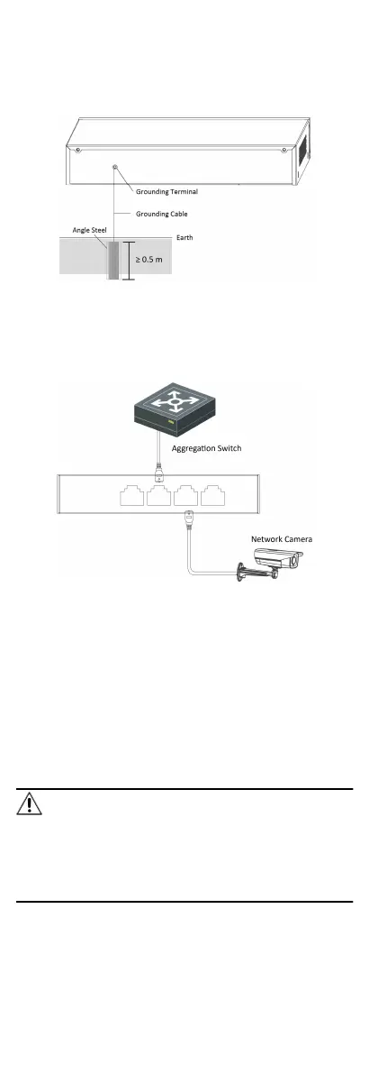
Weld one end of the grounding cable to the angle steel or steel
pipe and embalm the welding point via electroplang or
coang.
3.
Connect the other end of the grounding cable to the grounding
terminal.
Figure 3-2 Grounding with Angle Steel
3.2 Connecng RJ45 Port
Use a network cable to connect the device to the RJ45 port of a
peer device such as network camera, NVR, switch, etc.
Figure 3-3 RJ45 Port Connecon
3.3 Connecng SFP Opcal Module
Connecng SFP opcal module is supported when the device has
a
ber opc port or a combo.
When connected to a network cable, the combo is a RJ45 port.
When plugged into with an opcal module and connected to an
opcal ber, the combo funcons as a ber opc port.
When connected to both the network cable and
opcal ber at
the same
me, the port works as a ber opc port.
Steps
Cauon
•
Single-Mode opcal module needs to be paired.
•
Do not bend ber opc (curvature radius ≥ 10 cm) overly.
•
Do not look directly at ber opc connector because the laser
is harmful to eyes.
1.
Connect the two paired SFP opcal modules with an opcal
ber.
5
 Loading...