Figure 4-44 Mark the Screw Holes
6. Drill 8 holes according to the marks on the wall, and insert the
expansion sleeves into the screw holes. The suggested size of
hole is 6 (diameter) × 45 (depth) mm.
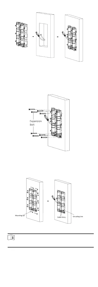
7. Fix the gang boxes with 8 expansion bolts.
Figure 4-45 Fix the Gang Boxes
8. Fill the gap between the gang box and wall with concrete.
Remove the mounng ears with tool aer concrete is dry.
Route the grounding line through the cable entries.
Figure 4-46 Remove the Mounng Ears
Note
The green-yellow line in the package is for grounding.
9. Connect cables and insert the modules.
32
 Loading...