Indicator
Refer to Indicator & Buzzer Status for details.
TAMPER
If the device is pulled o its base by force, the buon will pop out to trigger the tampering alarm.
Power Interface
12 VDC power supply
Note
Make sure the power supply connect correctly.
Network Interface
Connect to Ethernet.
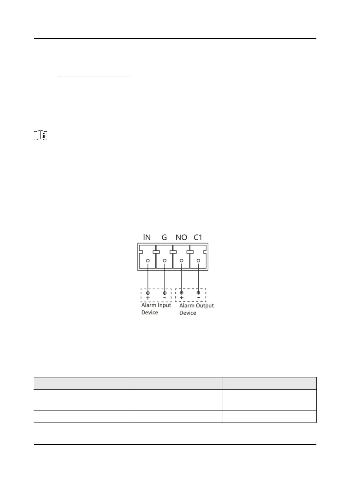
Alarm In/Out Interface
Pull out the green connector inside the Alarm In/Out Interface. Loosen the screws with a mini
sloed screrwdriver, put in the cable and ghten the screws. Plug the connector into the green
base.
Figure 3-4 Alarm In/Out Interface Illustraon
3.4 Indicator & Buzzer Status
Table 3-1 Indicator & Buzzer Status Descripon
Indicator Buzzer Status
Flashing green every 90
seconds
Disable Standby
Solid red Squeal Smoke/Temperature alarm
HF-VS409 Smoke Detected Camera User Manual
9