3 Product Description X-DO 32 01
Page 10 of 52 HI 801 097 E Rev. 4.00
3 Product Description
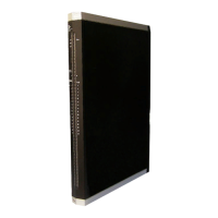
The X-DO 32 01 digital output module is intended for use in the programmable electronic
system (PES) HIMax.
The module can be inserted in any of the base plate slots with the exception of the slots
reserved for system bus modules. For more information, refer to the System Manual
(HI 801 001 E).
The module is equipped with 32 digital outputs that can be loaded with a nominal current of
up to 0.5 A per channel. With high level, a voltage equivalent to the supply voltage is
present on the corresponding output.
The outputs are suitable for connecting ohmic, inductive and capacitive loads and lamps.
The module has been certified by the TÜV for safety-related applications up to SIL 3
(IEC 61508, IEC 61511 and IEC 62061), Cat. 4 (EN 954-1) and PL e (EN ISO 13849-1).
Refer to the HIMax Safety Manual (HI 801 003 E) for more information on the standards
used to test and certify the modules and the HIMax system.
3.1 Safety Function
The module ensures its safety function using three safety switches connected in series for
each channel. This ensures that each output is two-fault-tolerant with respect to the safety
switch. Each safety switch of a channel can be individually switched off either via the
system bus (I/O bus) or via the second independent shutdown function (watchdog).
The safe output state is the de-energized state. Redundant processor systems monitor the
values expected for the outputs. Outputs that do not correspond to the expected values are
reset. The back-read branch is testable.
The safety function is performed in accordance with SIL 3.
3.1.1 Reaction in the Event of a Fault
If a channel fault occurs, the affected channel is set to the safe state. If a safety-relevant
fault occurs (e.g., multiple faults in one channel), the module adopts the safe state.
If the system bus fails, the outputs are de-energized.
The module activates the Error LED on the front plate.
3.2 Scope of Delivery
The module must be installed on a suitable connector board to be able to operate. If a FTA
is used, a system cable is required to connect the connector board to the FTA. Connector
boards, system cables and FTAs are not included within the scope of delivery.
The connector boards are described in Chapter
3.6, the system cables are described in
Chapter
3.7. The FTAs are described in own manuals.

 Loading...