FRONT OF THE DISPLAY MODULE | PAGE 6
2.1.3. DISPLAY BUTTONS
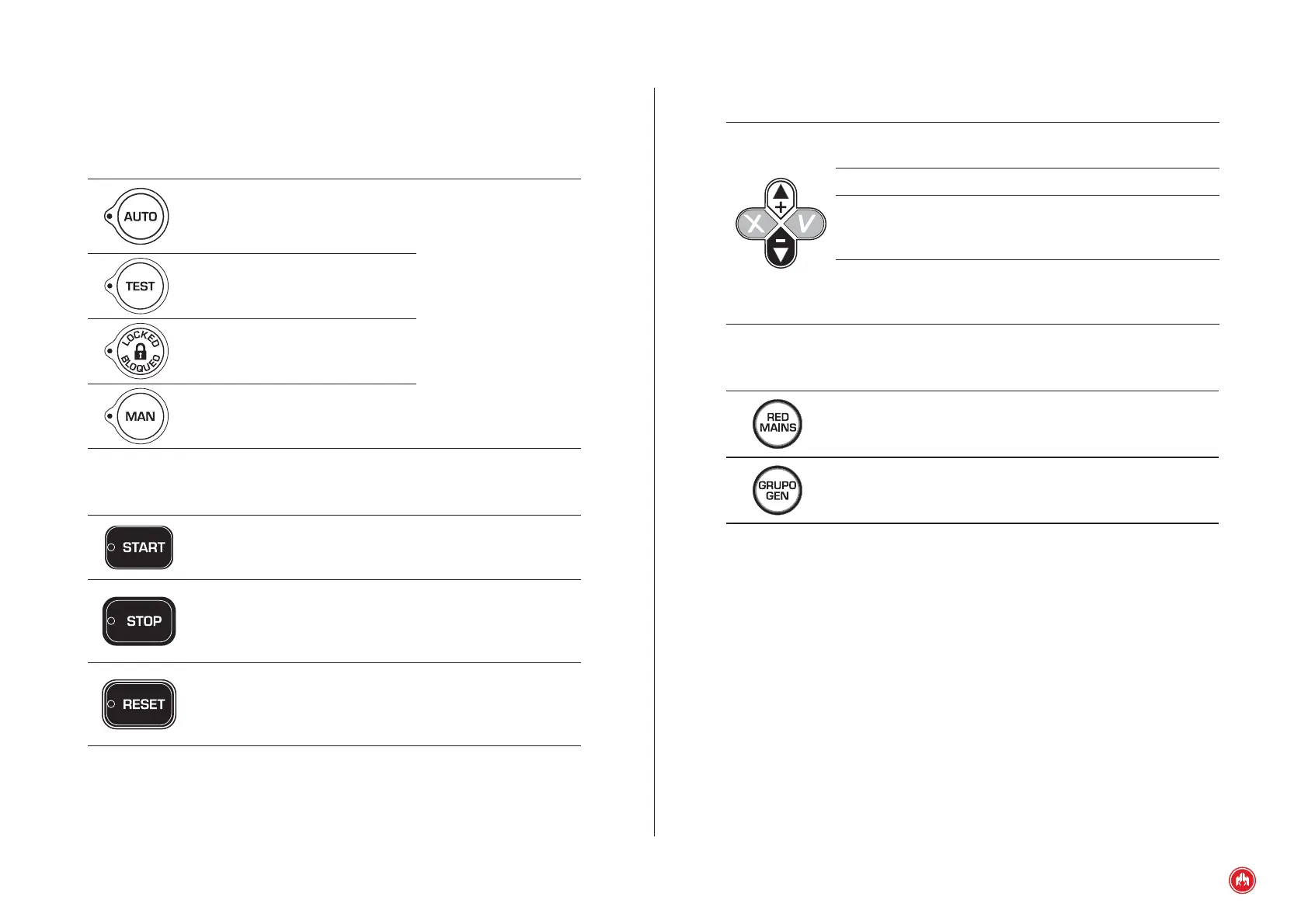
Confirm (V). Enter the menus and conrm the data
entered.
Cancel (X). Leave the menus and cancel the data entered.
Up (+). Advances through the selection of display screens,
the maintenance menus selection and increases the
programmed values.
Down (-). Go back through the selection on display screens,
the selection in maintenance menus and decrease the
programming settings.
2.1.4. CONTACTOR BUTTONS
Network contactor. Enables/disables the network contactor
(manual mode only).
Genset contactor. Enable/disable genset contactor (manual
mode only).
2.1 CONTROL UNIT BUTTONS
2.1.1. BUTTONS FOR CONTROL UNIT OPERATING MODES
Automatic mode. The control unit
monitors the status of the installa-
tion and manages its operation and
the programmable inputs.
Lit LED: Active mode.
LED flashing: Active
mode lock (automatic
and manual mode).
LED off: Mode not
active.
Test mode. The control unit starts
the engine while monitoring and
managing its operation.
Locked mode. The control unit
monitors the status of the installation,
but limits the startup of the engine.
Manual mode. The control unit is
commanded by the user.
2.1.2. CONTROL UNIT COMMAND BUTTONS
Engine start button (only in manual mode).
Manages start-up with one touch.
Lit LED: Engine started.
Engine stop button (only in manual mode).
The rst press stops the engine following a cooling cycle.
The second press stops the engine immediately.
Lit LED: Motor stopping (with or without cooling).
ALARMS RESET button.
Allows notication of the alarm by the user.
LED ashing: Alarms pending notication.
Lit LED: Alarms active.