DIMENSIONS, WIRING AND MECHANICAL PARTS | PAGE 17
The equipment must be isolated or disconnected before connecting the voltage
input for the generator, as there is a risk of danger.
The USB connector complies with the standard 2.0. To power the control unit, it
is recommended that a cable be used with a cross-section of 1 mm
2
.
A cable with a cross-section of 2.5 mm
2
must be used for +BAT, ARR, PR and PC
connections. For the rest of the connections it is recommended that a cable be
used with a cross-section of 1 mm
2
.
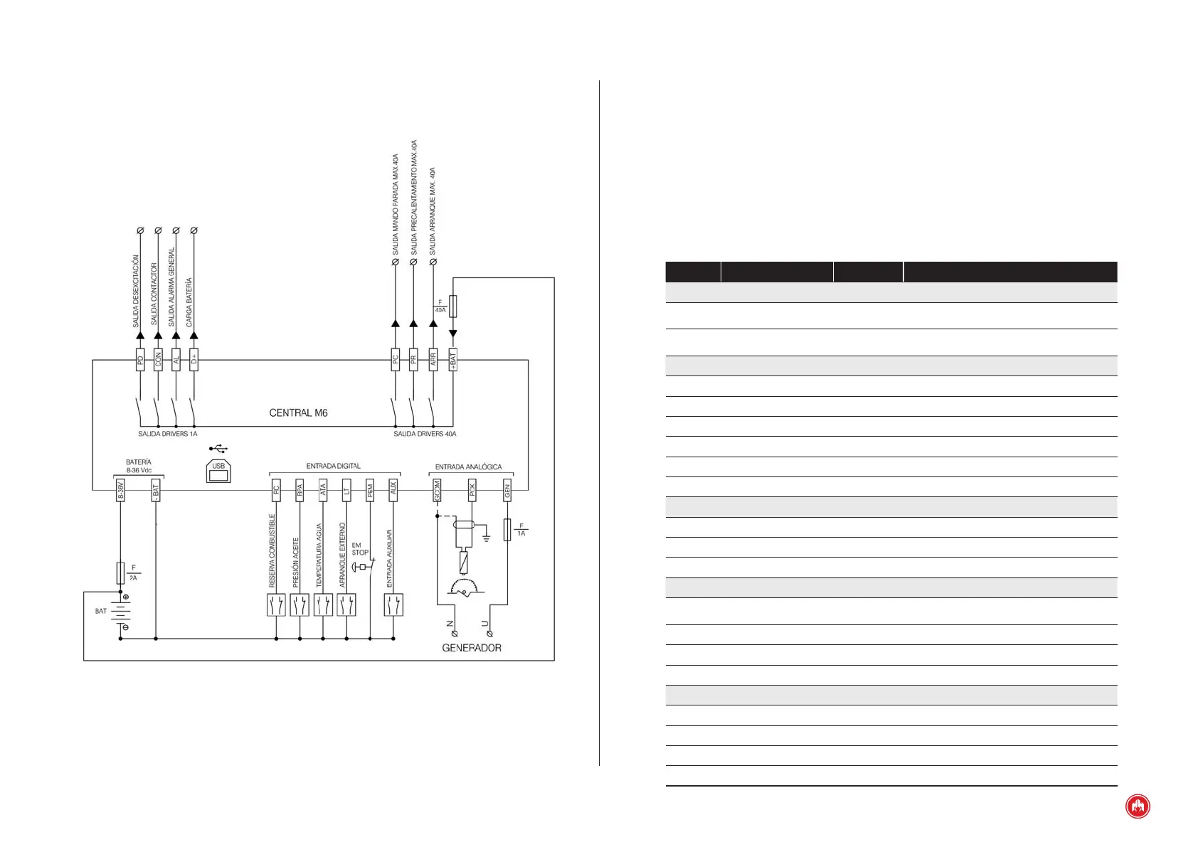
Fig.2
M1 control unit connections
5.1 INPUTS AND OUTPUTS
Signal Description Type Characteristics
Power supply
8÷36 V
Positive battery
terminal
Power supply Module supply voltage from 8 to 36 V
-BAT
Negative battery
terminal
Power supply Module supply negative
Digital inputs
RC Fuel reserve Inputs NPN digital input
BPA Low oil pressure Inputs NPN digital input
ATA High water temperature Inputs NPN digital input
LT External start-up Inputs NPN digital input
PEM Emergency Stop Inputs NPN digital input
AUX Auxiliary input Inputs NPN digital input
Pick-up / generator input
GCOM Common Inputs Pick-up and alternator voltage common input
PCK Pick-up Inputs PICK-UP input
GEN Generator Inputs Alternator voltage input
High-current PNP outputs
+BAT
Positive battery
terminal
Power supply Digital outputs supply voltage
ARR Start-up Output PNP digital output of power
PR Preheating Output PNP digital output of power
PC Congurable stop Output PNP digital output of power
Outputs PNP
D+ Alternator excitation Output PNP digital output
AL Alarm Output PNP digital output
CON Contactor Output PNP digital output
PD De-excitation Output PNP digital output