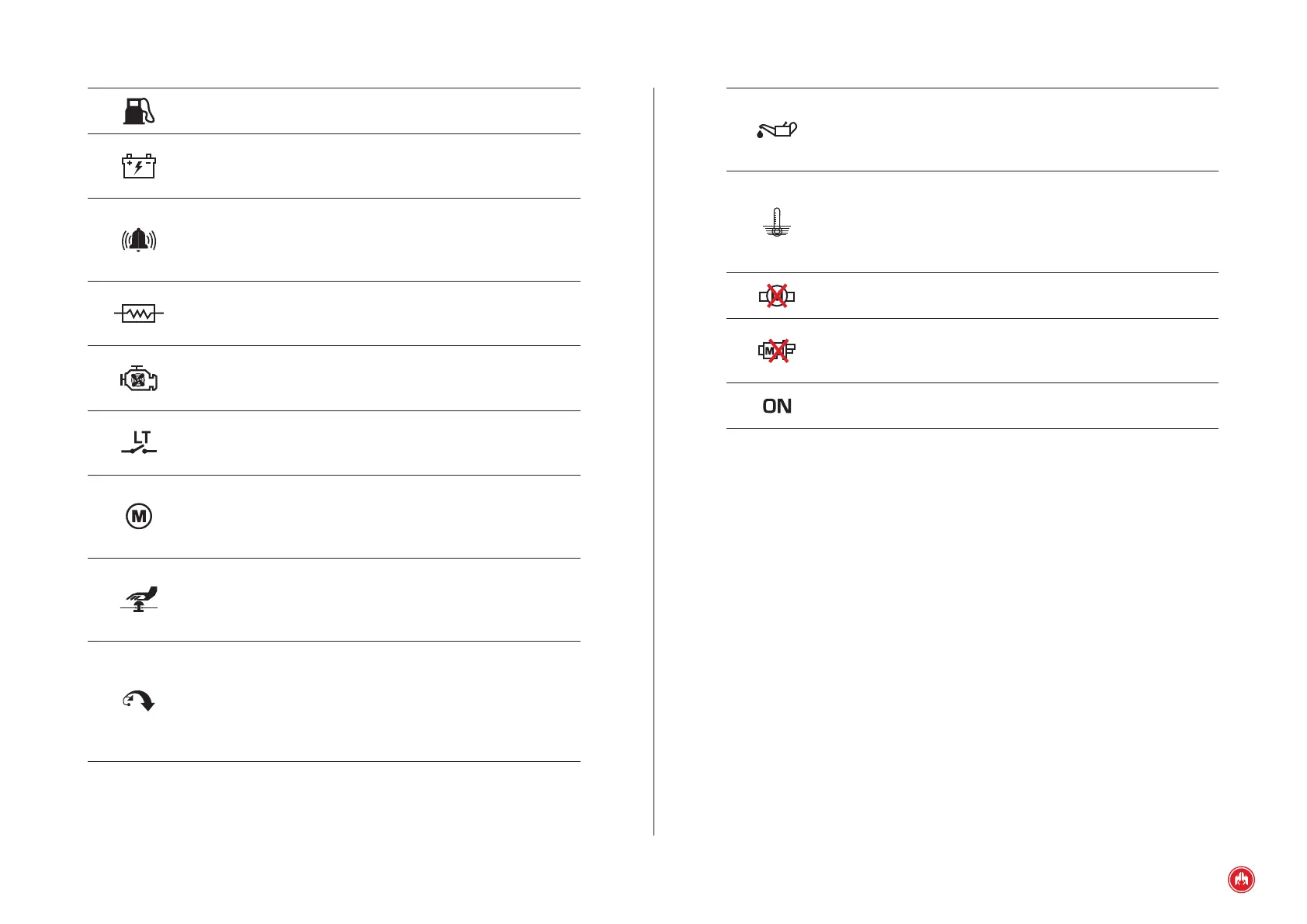
FRONT PANEL COMPONENTS | PAGE 6
Low oil pressure LED. This indicates that the engine’s
pressure switch has detected an abnormality. This protection
activates a timed shutdown cycle. The LED will remain lit while
the alarm condition persists and until the control unit is reset.
High water temperature LED. This indicates that the engine’s
thermostat has detected an abnormality in the running
temperature. This signal activates a timed shutdown cycle of
the genset. The LED will remain lit while the alarm condition
persists and until the control unit is reset.
Engine failure LED. This indicates that the engine has
stopped without the control unit having ordered it to stop.
Start-up failure LED. This indicates that after having made the
congured attempts to start the engine, the control unit has
failed to start it up.
Power supply. This optical signal indicates that the control
unit is turned on.
Fuel reserve LED. Indicates low level of fuel in the tank. This
indicator remains lit as long as the alarm condition persists.
Battery charging failure LED. This indicates that the battery
charge generator is not charging the battery. This indicator
remains lit as long as the alarm situation persists.
AUXILIARY alarm LED. This indicates that the alarm condition
established for the control unit’s auxiliary input has been
detected. This indicator remains lit as long as the alarm
situation persists.
PREHEATING LED. This indicator starts ashing at intervals of
approximately one second, during the preheating cycle
performed before each attempt to start the engine.
COOL STOP LED. This indicator starts ashing at intervals of
about one second when the control unit orders a shutdown
cycle. It does not turn off until the cycle comes to an end.
"LT" contact enabled LED. This signal is activated when the
free voltage contact is closed to earth and it turns off when it
is opened.
Engine running LED. This indicates that the engine is running.
The detection can be performed either by reading the D+ or by
reading the frequency. This latter can be done by generator
set or by Pick-Up.
EMERGENCY STOP LED. This indicator is activated when you
press the genset’s emergency stop. After the alarm condition,
it only turns off once the emergency stop has been rearmed
and the control unit has been reset.
OVERSPEEDING LED. This LED is activated by two conditions:
when the overspeed condition is not activated (see paragraph
3.2) and when the internal overspeed protection device turns
on. In the latter case, the control unit activates a timed
shutdown cycle and the optical indication will persist until you
reset the control unit.
 Loading...
