9
Chapter 2 Measurement Procedure
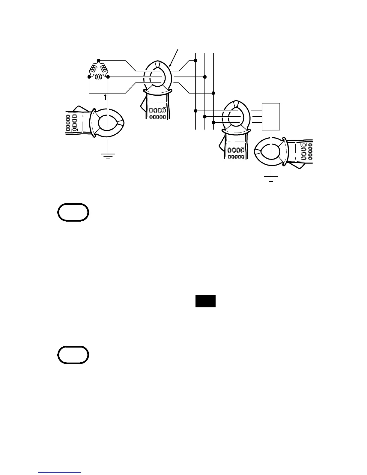
three-phase 3-lead
circuits
b
clamp all three leads of the circuit
b
Class 2 grounding line
a
E
2
Ig
a
E
3
Class 3 grounding line
Load
device
NOTE
NOTE
・ For measurement of single-phase 2-lead
circuits, clamp both leads of the circuit.
・ For measurement of three-phase 4-lead
circuits, clamp all four leads of the circuit. If
this is not possible, the measurement can also
be carried out on the ground lead of the
equipment.
3.Theeffectivevalue(
RMS
) of the leak current
is shown on the digital display. The selected
current range is shown at the bottom of the
display.
・ If a strong current (on the order of 100 A) is
flowing in an adjacent circuit, accurate
measurement may not be possible. Perform
the measurement at a sufficient distance from
other current-carrying conductors.
・ The frequency of special waveforms such as
at the secondary side of an inverter may not
be indicated correctly.