SERVICE & ROUTINE MAINTENANCE
CAUTION: maintenance and repairs must be carried out
by authorised personnel only. To prevent injury, always
remove the power cable from the power supply before
undertaking any work on the machine. Do not operate this
machine unless it is fully assembled and all guards are in
place. Use Hiretech genuine spare parts only.
General
1. Always make a list when first examining the machine, to
remind you of parts or action needed on completion of repair/
service.
2. The HT7-2 is subject to high speeds. All screws should be
fitted using a suitable thread lock compound.
3. On completion of any work or service on an electrical tool
or appliance statutory safety tests must be carried out by a
competent person and recorded (see Testing for Electrical
Safety page 8).
4. The HT7-2 needs no lubrication during routine servicing.
5. Always ensure that the electrical supply is disconnected
before starting any routine servicing or repair.
Visual Inspection
1. To clean the machine and remove dust, use a vacuum cleaner
to avoid damage and prevent inhalation of dust.
2. Examine all guards and mechanical parts for condition
including the Disc Guard Ref.54 which should be undamaged
and moving freely.
3. Examine the sanding pad, a worn or damaged pad must be
replaced to maintain performance and to avoid injury. There
must be a minimum of 4mm ( 3/16”) ‘tread depth’.
4. Examine the power cable for damage. If the outer insulation
shows the slightest of abrasions or the inner conductors are
exposed then the cable must be replaced. The cable must not
be repaired with tape or insulation sleeve.
5. Ensure all labels are sound, readable and secure.
6. Check that the castors are sound and moving freely. If a castor
is found to be loose or damaged then the ‘cutting’ angle must
be checked and reset as necessary (see Setting Castors page
7 and 8. Replace damaged castors.
7. Check the condition of the Bolt-Clamp Ref.59 and clean the
threads.
8. Check that the Wrench Ref.61 is in place and in good
condition.
9. If a cloth type bag is in service check the condition, clogged
dust bags or bags with holes make for inefficient dust pickup.
Dust Control
1. Turn the sander upside down and rest the machine on the
handles. Check the dust skirt for pieces of abrasive disc and
build up of dust. Clean as needed.
Drive
1. The dive gear does not require maintenance under normal
operating conditions.
Lubrication
1. The HT7-2 features sealed for life bearings which do not
require any lubrication. In the unlikely event that a bearing
has to be replaced use a Hiretech genuine spare part only as
the grease contained in the bearings is special. A standard
bearing is not suitable and may result in further damage.
2. Should the gearbox require service the gear housing and
gears must be cleaned thoroughly and the gearbox refilled
with grease Part No. 011270. This is a special grease
designed for the high speed and temperatures generated
within the gear box. Under no circumstance must a standard
automotive grease be used. Using such a grease will result in
gear failure and damage to the motor and other components.
The grease may also melt and leak from the gear box staining
the floor or work piece being sanded.
Care of Motor
1. The motor must be kept clean and free from grease and dust.
2. The motor brushes must be checked regularly. As it is necessary
to remove the Cover Motor Ref.4 during routine electrical
testing, it is then a simple matter to check the condition of the
motor brushes and avoid costly breakdowns.
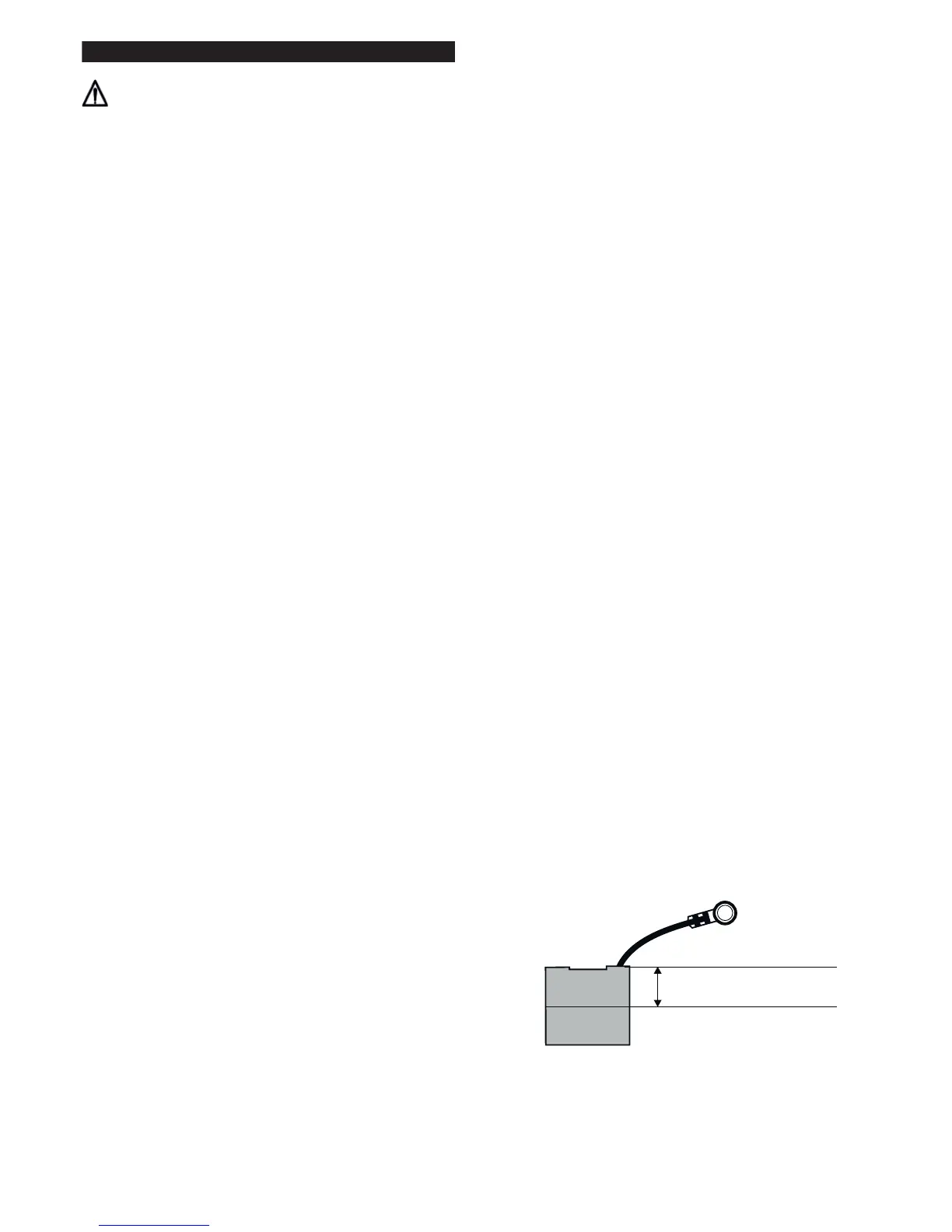
3. Replace ALL FOUR motor brushes when any one brush has
worn to 12mm (1/2”) or less in length. Brushes MUST slide
freely in the brush holders.
There is no need to remove or disconnect any internal leads
when changing the brushes, only the small braided shunt
(pigtail) is disconnected to release the brush.
4. To replace the motor Brushes Ref.12.
i. Remove the four Screws Ref.1 from the Cover Motor and
lift the cover off.
ii. Remove the four Spring Brush Ref.17 and set to one side.
The springs are removed by pushing the spring tag in
towards the brush and lifting out.
iii. Using a cross recess screwdriver remove the four brush
shunt (pigtail) retaining screws and lock washers Ref.16.
iv. Remove the four brushes.
v. Thoroughly clean the brush assembly and housing using a
soft brush and a suitable vacuum cleaner.
vi. Inspect the four brushes for damage or wear and if any
one brush is found to be damaged or worn to a length of
12mm (1/2”) or less then replace all four brushes. Always
replace all four brushes together.
Motor Brush
vii. When replacing brushes ensure that each brush moves
freely in each holder and fit the brush with
the shunt (pigtail) in such a position as to allow free movement
throughout the brush life. Ensure that each brush shunt is
connected securely with the Screw and Washer Ref.16.
(two spare screws and washers are provided with each
6
Minimum Brush Length
12mm ( /” )
1
2
 Loading...