Release the Speed Buttons, button 1 will now be
ON (yellow light). Disconnect from the power
supply, then reconnect to check that the green
power connected light does not flash when
connecting to the power supply to confirm the
reset has been successful.
Note: all four Speed Button lights will turn whenOFF
a run time reset is started.
4. The run time clock is built into the Speed Control
unit and will record the time the 8 runs. If theHT
handle assembly is used on another 8 it willHT
record the time that unit runs for. It is
recommended that the handle assembly is kept
with the same 8 at all times to accuratelyHT
record the run time for that 8.HT
General
1. Always make a list when first examining the
machine, to remind you of parts or action
needed on completion of repair/service.
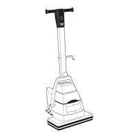
2. The 8 is subject to high speeds. All screwsHT
should be re-fitted using a suitable thread lock
compound.
3. On completion of any work or service on an
electrical tool or appliance statutory safety tests
must be carried out by a competent person and
recorded (see Testing for Electrical Safety page
8).
4. The 8 needs no lubrication during routineHT
servicing.
5. Always ensure that the electrical supply is
disconnected before starting any routine
servicing or repair.
Visual Inspection
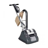
1. Check that the drum guard Ref.35 is in good
condition and functioning correctly. Ensure that
the Warning Label Ref.36 is present and legible.
2. Check all other guards and mechanical parts are
in good condition.
3. Examine the power cable Ref.39 and the handle
cable Ref.20. If the outer insulation shows the
slightest of abrasions or the inner conductors are
exposed, then the cable must be replaced. The
cable must not be repaired with tape or
insulation sleeve. Note that the Hiretech genuine
spare part has a non-marking insulation so that
the cable does not mark the floor during use.
4. Examine both the mains plug and the
interconnecting socket, Body Twist Lock Ref.24.
The plugs must be opened and examined (see
Electrical Testing page 8).
5. If a cloth type bag is in service check the
condition, old clogged cloth dust bags make for
an inefficient dust pickup.
6. Ensure that all labels are present and in good
condition.
Drive Belts
1. To examine the condition of the Drive Belts
Ref.164 and Ref.165 remove the four screws
Ref.83 and the Belt Guard Ref.81.
2. Lift the Fan Belt Ref.165 while rotating the pulley
to remove the fan belt. Repeat for the Drum Belt
Ref.164.
- take care to avoid trappingCAUTION
your fingers when removing or replacing
the drive belts.
3. Examine the pulleys for wear, worn or damaged
pulleys should be replaced
4. To reduce the instance of belt breakage, examine
the drive belts, look for cracks or fraying and
replace if necessary with new belts. To replace
reverse the above procedure taking care to avoid
bending the belts tighter than the pulley diameter
as this can result in damaged belts. Refit the belt
guard.
Dust Control System
1. For efficient dust pick up ensure that cloth type
dust bags are clean and unclogged and that the
intake is clear and properly adjusted.
2. Turn the machine on to its side and loosen the
three Screws Ref.71 and remove the Dust Shoe
Ref.72, check for and clear any obstruction. The
grit from the abrasive paper can wear away the
leading edge of the dust shoe, if this has
occurred then file or grind the leading edge
straight before refitting.
Install the dust shoe ensuring that the clearance
between the shoe and the drum is maintained
at10mm ( 3/8“).
Lubrication
1. The 8 is completely lubricated. The bearingsHT
are sealed and do not require lubrication. In the
unlikely event that a bearing requires
replacement use a Hiretech genuine spare part
only as the grease contained in these bearings is
special. A standard bearing is not suitable and
may result in further damage.
9