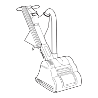
Sanding Drum.
1. Check that power supply is disconnected. Tilt the
machine back and rest the handle on the floor.
Open the drum guard and examine the drum
cover. A damaged or worn cover must be
replaced to maintain machine performance. A
damaged or worn cover can result in poor
sanding with subsequent damage to the floor
surface and can be dangerous in operation. A
cover that is worn to 1/4“ (6mm) or less in
thickness must be replaced.
2. To replace the drum cover see the detailed
instructions included in each genuine Hiretech
Drum Cover Kit Ref.167 Part # 162312. The use
of an impact screwdriver may assist.
3. It is recommended that at each service interval
the drum cover is checked and trimmed
(dressed) if necessary to provide a true uniform
diameter.
4. First check that the rear castors are properly
adjusted. Remove the 4 Screws Ref.83 and the
Belt Guard Ref.81. Check that the factory mark
is present and aligned on the rear castor adjuster
Ref.64 and main frame. Adjust as necessary by
loosening the two clamp Bolts Ref.65 and
adjusting the cam.
If the machine has no factory mark on the
adjuster and main frame then it is a later type
machine that uses a concentric support instead
of an adjuster. No adjustment is required.
Note: On earlier models the line stamped on the
adjuster and main frame has been set in the factory at
the time of manufacture. Never change, deface or
alter this line.
5. Fit a sheet of fine grit abrasive paper (120 grit),
abrasive side up on to a level floor surface.
Remove any abrasive paper from the drum and
re-tighten the clamp bar screws. Make sure the
clamp bar screws are tight.
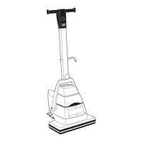
Position the floor sander over the abrasive paper
and connect the power cable to the power
supply. Tip the floor sander back to raise the
sanding drum off the floor and switch on.
Gently lower the floor sander so the sanding
drum 'just' touches the abrasive paper. Hold the
sander in position for a few seconds then tip back
and switch off.
Disconnect the power cable and tip the floor
sander back so that it rests on it's handle. Lift the
drum guard and check the condition of the drum
cover. If it is uniform an even surface will be
witnessed, if not, continue to dress the drum until
all high and low spots are removed. Take care
not to remove too much material as this will
reduce the life of the drum cover.
6. When a uniform surface is achieved it is
advisable to slightly ‘feather’ both edges of the
drum cover. Switch off and disconnect the power
cable from the power supply. Tilt the machine
back and lift the drum guard to expose the drum
cover. Using a medium to fine grit abrasive
paper carefully feather the edge of both sides of
the drum cover by holding the abrasive paper
against the edge and rotating the drum. Be
careful not to trap your fingers. The softer edge
provided will help prevent ‘cut’ lines witnessed
on the floor surface when sanding particularly in
softer woods. Always feather the edges of a new
drum cover.
WARNING - the sanding drum and drum
cover must be correctly adjusted and
maintained to ensure the best sanding
performance. Failure to do so can result
in damage to the floor surface and can
be dangerous.
Care of Motor
1. The motor must be kept free from grease and
dust. use high pressure air to blow theDO NOT
motor clean. Use a vacuum and soft brush to
clean the motor and brush block assembly.
2. The motor brushes must be checked regularly,
inspect the brushes every three months or every
300 hours from new and then every 100 hours of
use thereafter.
The 8 Multi-Speed has a run time clock builtHT
into the Multi-Speed Control Unit to assist in
scheduled servicing. See page 8 for information.
3. Replace motor brushes when any oneALL FOUR
brush has worn to 12mm ( / ”) or less in length.
15
32
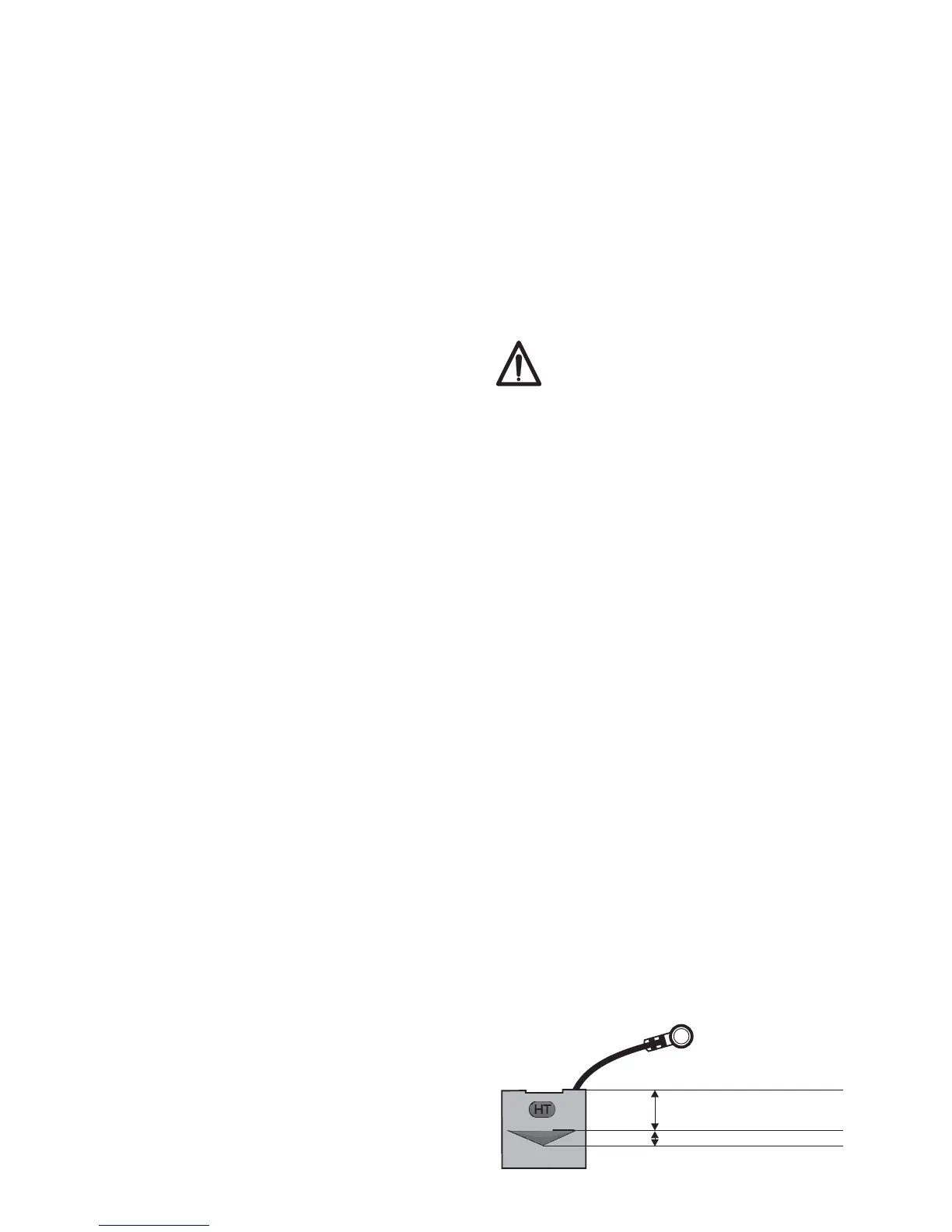
Brushes slide freely in the brush holders.MUST
Brush ware is also indicated by the ‘triangular’
ware indicator stamped on genuine Hiretech
motor brushes marked with the symbol. SeeHT
illustration below.
When any one motor brush is worn down to the
ware indicator inspect the brushes ever 100hrs.
Replace all four motor brushes when any ONE
(1) motor brush is worn down to the minimum
brush length as indicated by the bottom of the
triangle stamped on the motor brush.
10
HT
HT MOTOR BRUSH8
Minimum Brush Length
12mm ( / ”)
15
32
Ware Indicator