Electrical Testing
CAUTION - testing for electrical safety
should be undertaken by a competent
person and all results recorded. Do not
exceed 1250 volt insulation test duration
of 3 seconds.
1. Examine the power cable and handle cable for
damage, if the outer insulation shows more than
the slightest of abrasions or the inner conductors
are exposed then the cable must be replaced.
The cables must not be repaired with tape or
insulation sleeve.
2. Open and check mains plug and
interconnecting socket Ref.24 for condition,
loose connections, damaged wires etc. Ensure
that the strain relief of the power cable plug is
correctly secured to the outer cable insulation.
3. Open and examine the Switch Housing Ref.11
for loose connections, damaged wires, and
general condition. Pay special attention to any
gaskets, 'O' rings and seals intended to exclude
dust from the switch and switch housing area,
these must be maintained in good condition.
Examine the soft key pad that is located in the
switch cover, ensure this is in good condition and
the surface is not punctured or damaged.
4. Ensure that the Strain Relief Ref.5 is correctly
secured to the outer cable insulation.
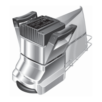
5. For the 8 fitted with a Multi-Speed ControlHT
and 8’s fitted with a low volt circuit breakerHT
type switch use a trailing test cable (see part
information below) that connects the testing
equipment directly to the machine body Base
Twist Lock Ref.23 This allows the body of the 8HT
to be tested separately from the handle
assembly.
Part No. 024500 Test Lead
(use for all regions excluding North America)
Part No.:024502 Test Lead ( )NA
(use for North America only)
CAUTION HT- the 8 Test Lead does not
have the ( ) conductorLIVE HOT
connected. Only the andNEUTRAL
EARTH are connected at the plug end
and the NEUTRAL AND EARTH
connected at the Body Twist Lock end.
There is also a shunt fitted in the body
twist lock to short the andLIVE NEUTRAL
terminals to allow a full dielectric test.
THIS TRAILING TEST LEAD CANNOT BE
USED FOR FUNCTIONAL TESTING.
6. Replace the switch cover taking care to avoid
trapping leads and ensuring that the dust gasket
is correctly positioned.
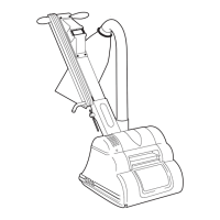
7. Place the handle assembly on the test bench then
using standard procedure test for electrical safety
(1 )CLASS EARTHED APPLIANCE
1250DO NOT EXCEED VOLT FLASH
DURATION SECONDS3.
.RECORD THE TEST RESULTS
8. Now Place the machine body safely on the test
bench and connect the Test Lead to the Base Twist
Lock Ref.23 and connect the other end to the test
equipment. Then using standard procedure test
for electrical safety.( 1CLASS EARTHED
APPLIANCE)
1250DO NOT EXCEED VOLT FLASH
DURATION SECONDS3.
.RECORD THE TEST RESULTS
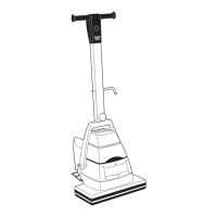
9. You have now tested both the handle assembly
and the machine body, if both show good test
results then you can carry out a functional or run
test if required by placing the complete machine
in a secure position and switching the machine
on.
- when undertaking aCAUTION
functional test ensure that the machine is
secure, remember the sanding drum will
rotate, ensure that the drum cannot come
into contact with the work bench/service
area.
10. Ensure that the switch trips to ‘ ’ when theOFF
current is interrupted. During complete machine
functional test with the machine switched on and
running. Switch off the electrical supply at the
supply socket then when the machine has
stopped - switch it back on at the socket. Note
that the machine has tripped to and theOFF
speed button one (1) is illuminated. You must
now press and hold the / (I/O) button forON OFF
1.5secs to turn the machine .ON
If this function fails to operate do not use the
machine. Report/repair fault and retest.
13