Programming
© 2008 HIRSCHMANN Automation and Control GmbH · Branch Office Ettlingen · eMail: info.ecs@hirschmann.de · www.hirschmann-usa.com 34
50 650 19 0201e_Rev C (LinkBelt278).doc / 2008-08-18 / Rev. C / rk
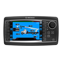
4.3.4.2 Working Area Limitation - Virtual Wall (if equipped)
Programmable function for the limitation of the working area by up to 5 virtual walls.
The work area definition system helps the operator to define the crane’s working area. This is done by creating
vertical wall(s) that can represent obstacles (i.e. buildings, towers, poles, etc.) in the crane’s working range. The
wall(s) are set by defining points with the boom tip along the outer limits of the operator’s work area, see setup
procedure below. Because these walls are defined by the operator and are not “actual real” walls, we refer to
them as “virtual” walls. When setting the walls, always keep a safe working distance to any obstacles. Never
work outside a safe working area as outlined by common practice, standards, and manuals.
A virtual wall is set by defining two points.
To prevent inaccuracies when defining the two points for the virtual wall, use the following two rules:
1. The two points should be the same distance from the obstacle.
2. Set the two points at the maximum distance apart, which can be safely reached by the boom tip.
The operator can setup up to 5 virtual walls, the first wall is defined by a straight line between two set points.
The second through fifth walls are created by one new point and the previously selected point. After the walls
have been set, the system alerts the operator when the boom approaches them. This is done both visual and
audible. Similarly, the “virtual wall” symbol in the main screen blinks.
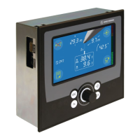
Calling up the function:
back to normal LMI working screen
edit radius limit
edit tip height limit
edit main boom angle limit
edit slewing angle limit /
virtual wall
>>