12
MR6DE User Manual
Installation Guide
B
A
|
A-B
|
PP
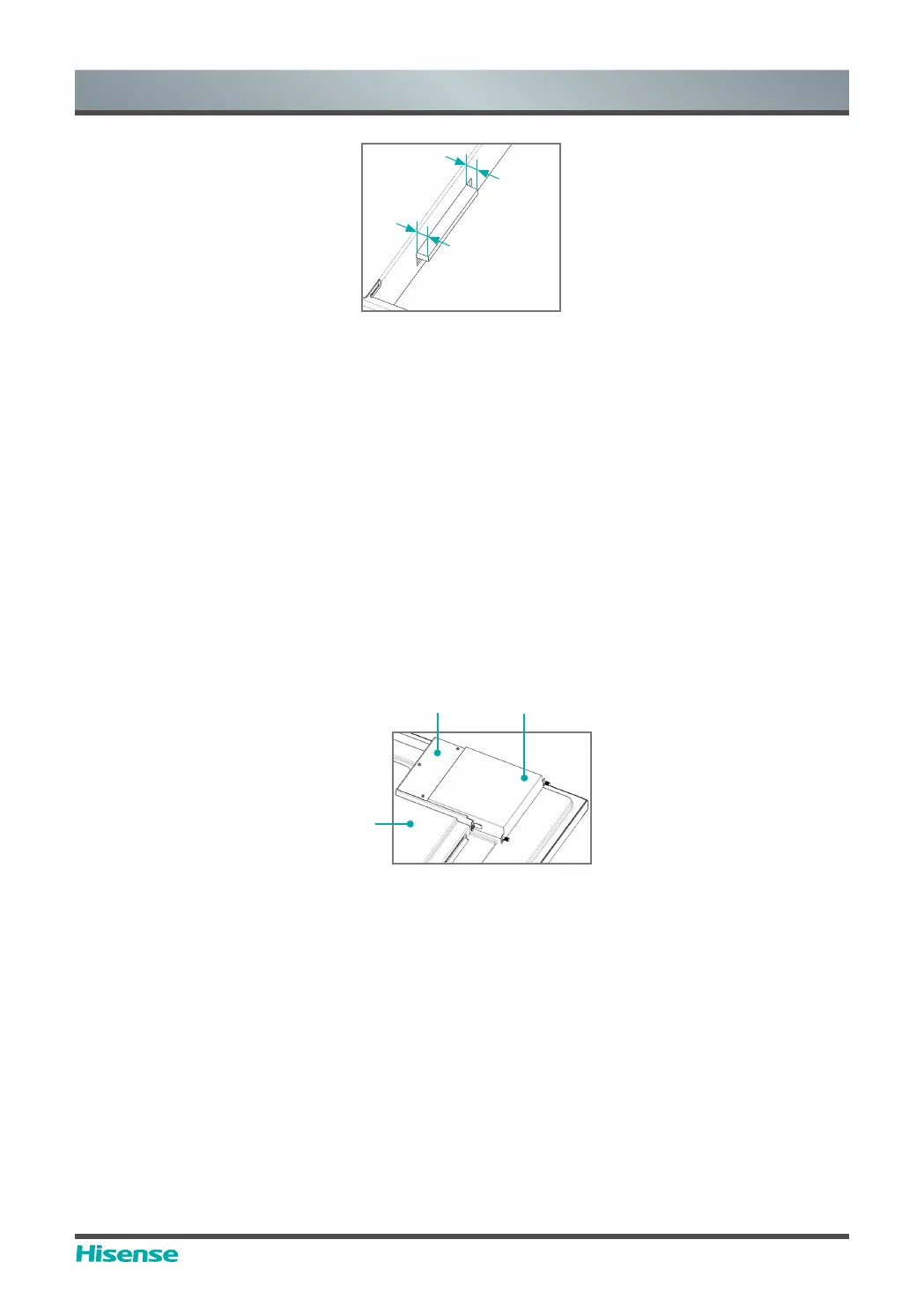
Instructions for OPS terminal assembly
tolerances
(2) Instructions for assembly routes:
a. Place the touch screen vertically or place the touch screen face-down stably, and make sure
there is enough room for operation around the computer bracket on the back of screen.
b. Remove M3x6 screw reserved at
ķ
for standby application.
c. Insert OPS-C Plus computer into the computer bracket along the route as shown in the
Figure until
ĸ
and
ķ
are in close contact.
d. Apply spare screws M3x6 to fasten the computer (some computer models come with screws
WKDWFDQEHXVHGGLUHFWO\WLJKWHQLQJWRUTXH1P01P
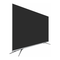
(3) The pattern after assembly is as follows:
Computer bracket
Touch Screen
(back side)
OPS-C Plus computer
Schematic diagram after the
assembly of OPS-C Plus computer
(4) Precautions after assembly:
a. After the computer is installed,
ĸ
and
ķ
should be closely fitted (same on the left and right
sides).
b. Screws are firmly and securely fastened. The computer doesn't shake.
4. After the above steps are completed, screen can be switched on. After startup, OPS computer
is started, and the operating system interface is performed to confirm that there is no abnormality.
The first startup is completed.