--- 16 ---
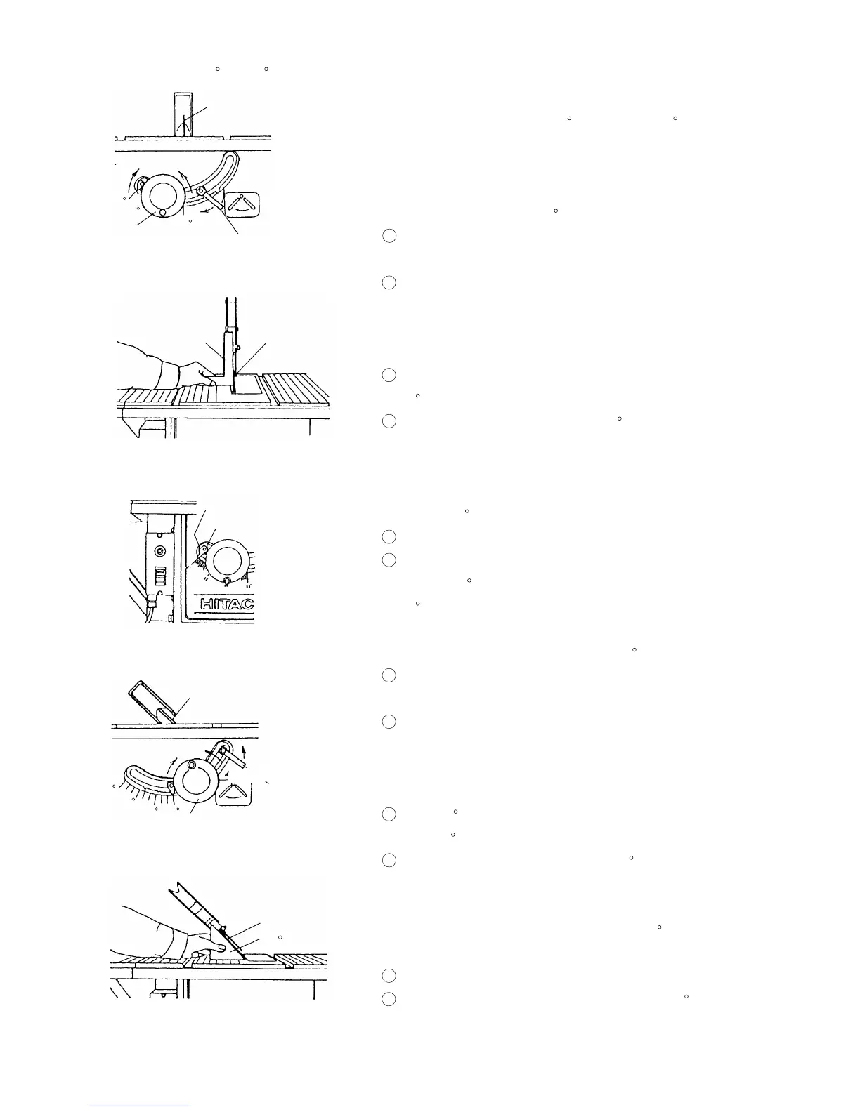
8-3-2. Adjusting the 90 and 45 Positive Stops
Saw blade
Up
Wheel
Fig. 16-a
Down
Loosen
Square
Fig. 16-b
Saw blade
Tighten Tilt lock handle
0
45
15
The tool is equipped with positive stops for rapid and accurate
positioning of the saw blade at 90 and left bevel 45 to the
table.
Check and adjust the positive stops with the following
procedures.
(1) To adjust positive stop at 90
1 Turn the wheel fully clockwise and set the saw blade to the
maximum cutting height.
2 Loosen the saw blade tilt lock handle and move the saw
blade tilting mechanism to the left until it hits against the
stopper. Then tighten the saw blade tilt lock handle (see
Fig. 16-a).
3 Use a square to check that the saw blade is at precisely
90 (see Fig. 16-b).
4 If the saw blade is not at precisely 90 , loosen the saw
blade tilt lock handle by turning it counterclockwise.
Loosen the M6 x 20 seal lock screw (see Fig. 15-c) a few
turns and move the saw blade tilting mechanism until the
blade is 90 to the table (see Fig. 16-b).
5 Tighten the saw blade tilt lock handle after adjustment.
6 Loosen the 5 mm machine screw and set the needle
pointer to 0 . On completion of adjustment, recheck the
90 angle of the saw blade and table (see Fig. 16-c).
(2) To adjust the positive stop at left bevel 45
1 Turn the wheel fully clockwise and set the saw blade to the
maximum cutting height.
2 Loosen the saw blade tilt lock handle and move the saw
blade tilting mechanism to the right until it hits against the
stopper. Then tighten the saw blade tilt lock handle
(see Fig. 17-a).
3 Use a 45 gauge to check that the saw blade is at a left
bevel 45 (see Fig. 27-b).
4 If the saw blade is not at a left bevel 45 , loosen the saw
blade tilt lock handle. Loosen the M6 x 20 seal lock screw
(see Fig. 15-c) a few turns and move the saw blade tilting
mechanism until the blade is at left bevel 45 to the table
(see Fig. 17-b).
5 After adjustment, tighten the saw blade tilt lock handle.
6 On completion of adjustment, recheck the left 45 bevel of
the saw blade to the table.
Needle pointer
Fig. 16-c
5 mm Machine screw
Fig. 17-a
Saw blade
Fig. 17-b
45 Gauge
Saw blade
Up
Wheel
Down
Loosen
Tilt lock handle
0
Tighten
15
30 45
 Loading...