11
CP-X2511N(C15I-25N2) / CP-X3011N(C15I-30N2) / CP-X4011N(C15I-40N2) / CP-X2011N(C15-20N2) / ED-X45N(C15-20N2)
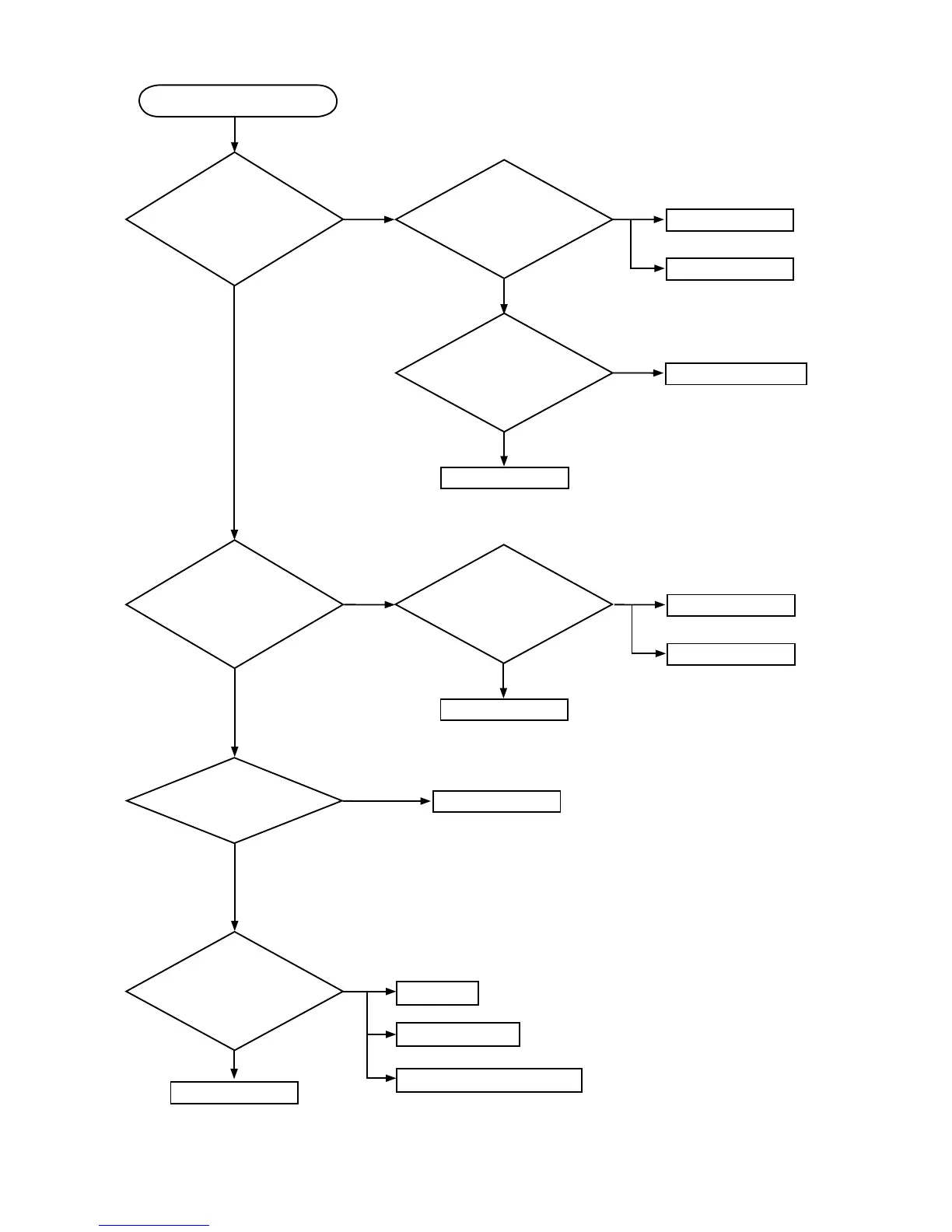
Power can not be turned on
Are
voltage
supplied at pins (3)
and (5) of E800 on the PWB
assembly MAIN in standby
mode?
Are volt-
age supplied at pins
(1), (7), (9), (11) and (19) of
E800 on the PWB assembly
MAIN in standby
mode?
NO
YES
(3): +15V
(5): GND
Does
LAMP (D303) or
TEMP (D302) indicator light
or blink?
YES
(1): +5V
(7): +17V
(9): GND(for +17V)
(11): +6.0V
(19): GND
NO
*: Be sure to unplug the power cord before measuring resistance.
Measure resistance*
between pins (3) and (5) of
E800.
Disconnect TSW
from power unit circuit, and
measure resistance of
TSW.
Open
0Ω
PWB assembly MAIN
Power unit (circuit)
Thermal switch (TSW)
Open
Power unit (circuit)
NO
Measure
resistance* between pins
(1) and (19),between pins (7) and (9),
and between pins (11) and (19)
of E800.
0Ω
PWB assembly MAIN
Power unit (circuit)
Power unit (circuit)
Open
Go to the next page
PWB assembly MAIN
YES
Measure
resistance* between
pins (1) and (2) of S801 when
the lamp door is secure.
Lamp door
Re-attach lamp door
Re-attach PWB assembly MAIN
Open
0Ω
0Ω
 Loading...