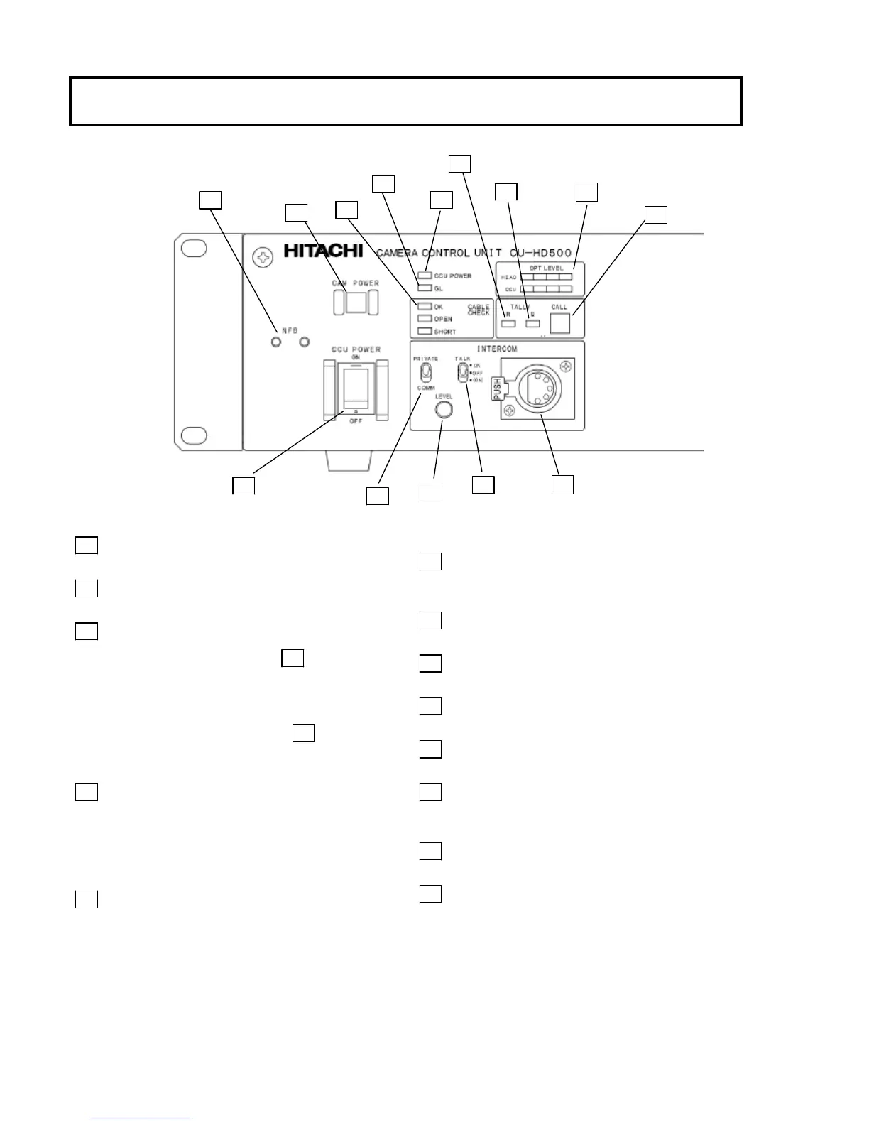
Facility names and functions (Front)
1 CCU POWER switch
CCU power on/off switch.
2 CCU POWER LED
Lights when power is on.
3 CABLE CHECK LED
OK: CAMERA POWER switch 4 can be
operated.
OPEN: Fiber cable not connected.
SHORT: Excess current in fiber cable.
Note: CAMERA POWER switch 4 is
inoperative when OPEN, SHORT LED is
lighted.
4 CAMERA POWER switch
Camera power on/off switch; lights at power on.
When the camera power is off, only one channel
intercom (CH1) is available.
Press the switch for 3 sec. or more, the camera power
turns off.
5 GL ON LED
Note: When a different frame rate signal is input
for genlock, the LED blinks and the signal is ignored.
6 R TALLY LED
Lights at red tally input or when sending CALL
signal from camera.
7 G TALLY LED
Lights at green tally input.
8 CALL button
Press to call the camera.
9 INTERCOM LEVEL control
Adjusts intercom listening volume.
10 TALK ON/OFF switch
Intercom microphone on/off switch.
11 PRIVATE/COMM switch
PRIVATE: Communicate with camera only
COMM: Communicate with entire system
12 Intercom connector (XLR,5P)
Connection for optional MT-12MF headset.
13 NO FUSE BREAKER (NFB)
8