EasyManua.ls Logo

Hitachi CU-HD500 - Service Information; Connector Pin Diagrams

Hitachi CU-HD500
37 pages
Print Icon
To Next Page IconTo Next Page
To Previous Page IconTo Previous Page
Loading...
16
PUSH
12
3
Service information
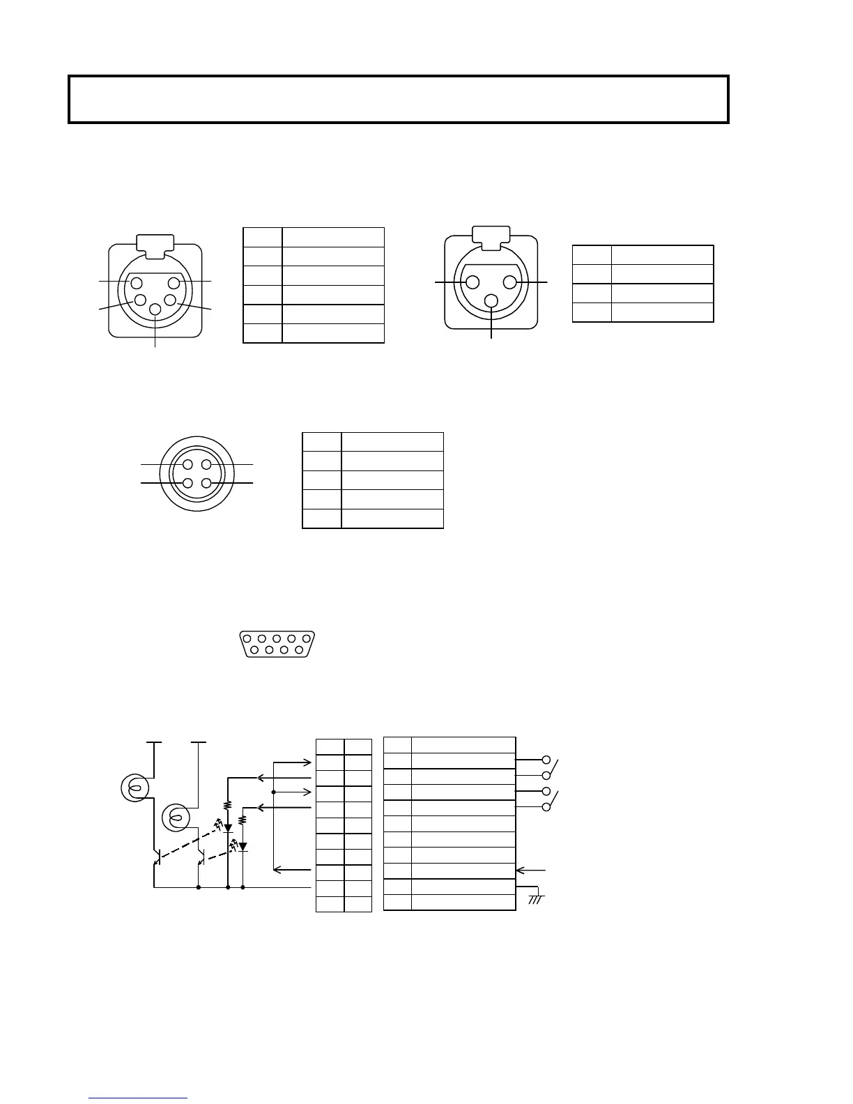
Connector pin diagrams
INTERCOM (5 pin XLR female:HA16PRH-5S) MIC OUT 1,2 (3 pin XLR male:HA16RM-3SE)
Remote 1,2 (4 pin female:HR10A-7R-4S(73))
Combined connector: HR10A-7P-4P
TALLY OUT(9pin D-sub female:RDED-9S-LNA(4-40)(55))
15
9 6
Application circuit example Plug CU mainframe Internal circuit
Pin
Signal
1 TALK (C)
2 TALK (H)
3 RECEIVE (C)
4 RECEIVE L (H)
5 RECEIVE R(H)
Pin
Signal
1 MIC GND
2 MIC(H) IN
3 MIC(C) IN
Pin
Signal
1 +12V output
2 DATA input
3 DATA output
4 DATA ground
Pin
Signal
1
R TALLY 1
2
R TALLY 2
3
G TALLY 1
4
G TALLY 2
5
6
7
NC
8
+24V
9
GND
-
Pin
1
2
3
4
5
6
7
8
9
-
PUSH
15
3
4 2
1
23
4
24V
10mA max
+24V power current of pin 8 is max.10mA.
Vcc Vcc

Related product manuals