Number Item Description
1 LAN board Networking board
2 LAN1 Connects to maintenance PC
3 LAN2 Connects to user's network
4 Uninterruptible power
supply port
Not used.
2. Connect the other end of the cable to a management console.
Step 5: Power on the storage system
After connecting the management console to the storage system, you can power on the
storage system.
Procedure
1. Power on the PDUs.
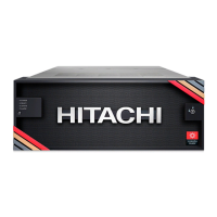
2. Conrm that the top (POWER) LED on the lower left front side of the controller is lit
amber, as shown in the following gure. If the storage system has a drive tray,
conrm that the POWER LED on the lower left front side of the drive tray is lit green.
Item Description
1 POWER LED on the front of the controller
3. If the front bezel is not attached to the front of the controller, attach it as follows:
a. Line up the two tabs on the left side of the controller with the two slots on the
left side of the bezel.
b. Connect the bezel by sliding it on and swinging the bezel closed.
c. Use the key to secure the bezel to the front of the unit.
4. On the lower left front side of the controller, press and hold the POWER ON/OFF
button until the POWER LED changes to green (about 3 seconds), and then release
the button.
Step 5: Power on the storage system
Installing your VSP E590 and VSP E790 storage system
Hitachi Virtual Storage System E590, E790 Installation Guide 9

 Loading...