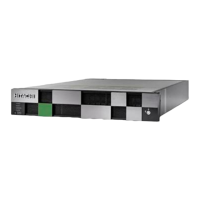
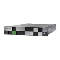
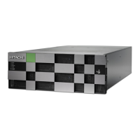
CBSS controller power supply unit LEDs and connectors
The following table describes the denitions of the CBSS controller AC power supply unit
LEDs and connectors.
Number Item Description
1 Receptacle Connects to the power
cable provided with the
storage system.
2 AC IN LED Blue: AC input is normal.
3 ALM / RDY LED Red: Power supply unit can
be replaced.
Green: Normal operation.
Host, Network, and Drive Tray Ports and LEDs
The controllers are equipped with specic interfaces for connecting, powering,
conguring, and managing the storage system. The component LEDs display the
operating status of the storage system.
Front-end modules
The front-end modules (FEMs), also called channel boards (CHBs), control the transfer of
data between the host and cache memory. VSP G130, G/F350, G/F370, G/F700, G/F900
storage systems support Fibre Channel (FC) and iSCSI FEMs for attachment to host
servers. The front-end module LEDs indicate the operating status of the module.
CBSS controller power supply unit LEDs and connectors
Chapter 2: System controllers
Hitachi Virtual Storage Platform F350, F370 Hardware Reference Guide 18

 Loading...


