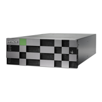
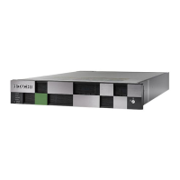
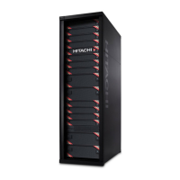
Do you have a question about the Hitachi Virtual Storage Platform F900 and is the answer not in the manual?
Introduces the BECK tool for cabling path checking and its availability.
Step-by-step procedure for downloading and installing the BECK tool.
Provides instructions on how to launch the BECK tool application.
Describes the layout and activation of Logical and Physical areas in the configuration screen.
Outlines methods for creating new configuration diagrams automatically or manually.
Details procedures for editing logical configuration figures, including assigning units.
Explains how to assign units, change drive trays, edit box codes, and move units in logical configurations.
Details procedures for editing physical configuration figures, including setting rack size.
Describes how to set drive trays in empty racks or change/delete existing drive trays.
Explains how to set controllers, edit box codes, and manage DKB options.
Details the process of moving and exchanging units within the BECK tool configuration.
Explains how to interpret and use the cable figures generated by the BECK tool.
Explains the functions of buttons and fields in the Cable Figure.
Details how to use features like Standard, Path, Route, and Box Code in the Cable Figure.
Guides on expanding a configuration by loading a simple trace file.
Describes how to save and load configuration files using the BECK tool.
Lists common error messages from the BECK tool and their corrective actions.
Continues listing BECK tool error messages and corrective actions.
Provides special guidelines, configuration rules for dense intermix drive trays, and yellow box indicators.
Specifies power outlet needs, voltage ranges, and power supply redundancy for controllers and drive trays.
Advises on planning redundant power circuits and rating them appropriately.
| Model | Virtual Storage Platform F900 |
|---|---|
| Form Factor | Rack-mountable |
| Storage Controller Type | Active-active |
| Supported Drives | SSD, HDD |
| Data Reduction Features | Deduplication, Compression |
| Dimensions (H x W x D) | Varies by configuration |
| Weight | Varies by configuration |
| Category | Enterprise Storage |
| Protocols Supported | Fibre Channel, iSCSI, FCoE |
| Data Protection | RAID, replication, snapshots |
| RAID Level | RAID 5, RAID 6 |
| Maximum Capacity | 32 PB |
| Drive Types Supported | SAS SSD, SAS HDD, NL-SAS |
| RAID Levels Supported | RAID 5, RAID 6 |
| Host Interfaces | FC, FCoE, iSCSI |
| Operating System Support | Windows, Linux, UNIX |
| Power Supply | Redundant power supplies |
| Cooling | Redundant cooling fans |
| Warranty | 3 years |
| Storage Type | All-Flash, Hybrid |
| Installed Devices / Modules Qty | Varies by configuration |


 Loading...