Number Item
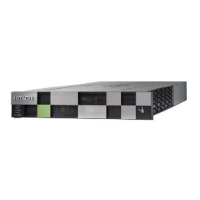
1
NAS module
2
Front end module
3
Back end module
4
LAN blade
5
Power supply unit
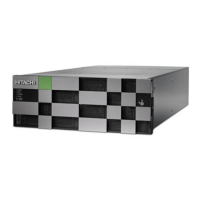
CBLM power supply unit LEDs and connectors
The following table lists the definitions of the CBLM power supply unit LEDs
and connectors.
Number
Item Description
1
ALM/RDY LED Red: Power supply unit can be
replaced.
2
Receptacle Connects to the power cable
provided with the storage
system.
3
RDY LED Green: Normal operation.
Host, Network, and Drive Tray Ports and LEDs
The controllers are equipped with specific interfaces for connecting,
powering, configuring, and managing the storage system. The component
LEDs display the operating status of the storage system.
Front end module descriptions
The front end module LEDs display the operating status of the module.
28 Virtual Storage Platform G400, G600 controller
Hitachi Virtual Storage Platform G400, G600 Hardware Reference Guide
 Loading...