Connecting the Inverter to ModBus
Appendix B
B–4
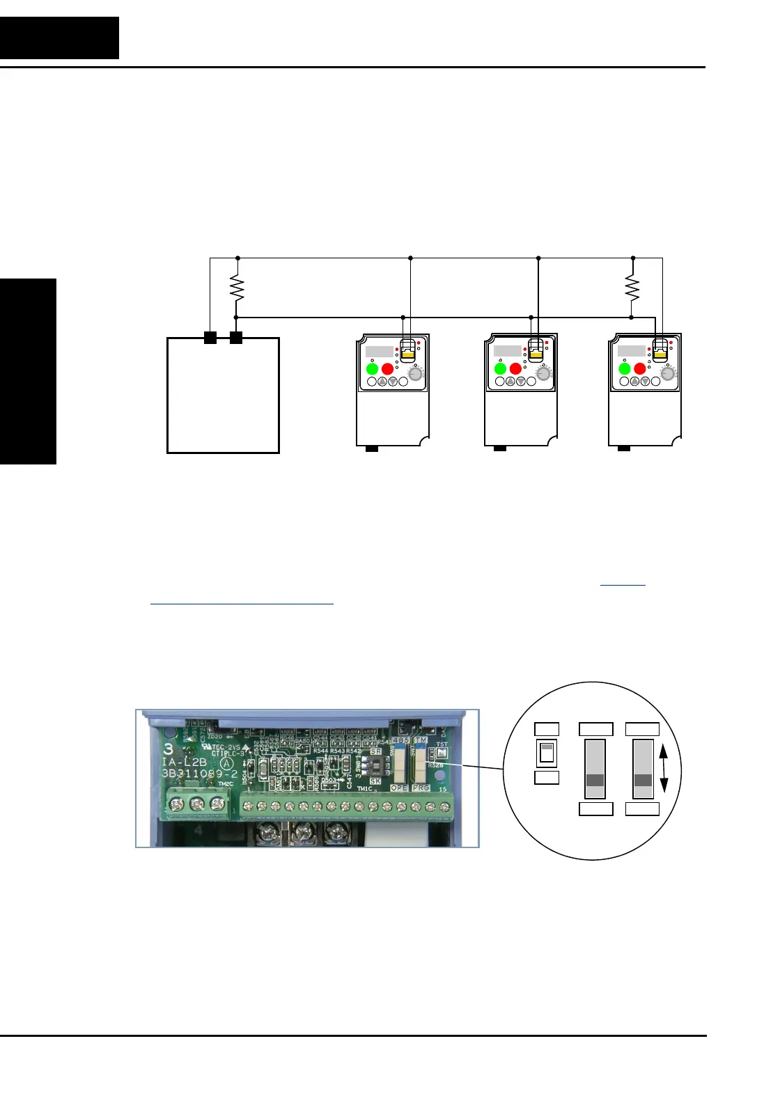
4. Terminate Network Wiring - The RS-485 wiring must be terminated at each
physical end to suppress electrical reflections and help decrease transmission errors.
The L200
2 communications port does not include a termination resistor. Therefore,
you will need to add termination to the inverter if it is at the end of the network
wiring. Select termination resistors that match the characteristic impedance of the
network cable. The diagram below shows a network with the needed termination
resistor at each end.
5. Set Inverter OPE/485 Switch - The inverter serial port accepts a connection to either
a remote keypad device or to the network. You will need to set the DIP switch on the
inverter to configure the port for ModBus communications. Setting the switch will
require removing the front housing cover. Remember to power OFF the inverter
before removing the cover or changing the DIP switch setting. Refer to “
Front
Housing Cover” on page 2–3 for detailed instructions.
Locate the OPE/485 DIP switch as shown in the figure below. Carefully move the
switch to the upper position labeled “485” (slide in direction of arrow). Then replace
the front housing cover.
At this point the electrical network connection is complete. The next step will show
how to configure parameters and settings related to ModBus communications.
L2002
1
2
RUN
STOP
RESET
FUNC.
STR
HITACHI
POWER
ALARM
RUN
A
Hz
PRG
5 0.0
L2002
1
2
RUN
STOP
RESET
FUNC.
STR
HITACHI
POWER
ALARM
RUN
A
Hz
PRG
5 0.0
L2002
1
2
RUN
STOP
RESET
FUNC.
STR
HITACHI
POWER
ALARM
RUN
A
Hz
PRG
5 0.0
ModBus
Network
Host device
SP SN
SR
SK
OPE
485
PRG
TM