6
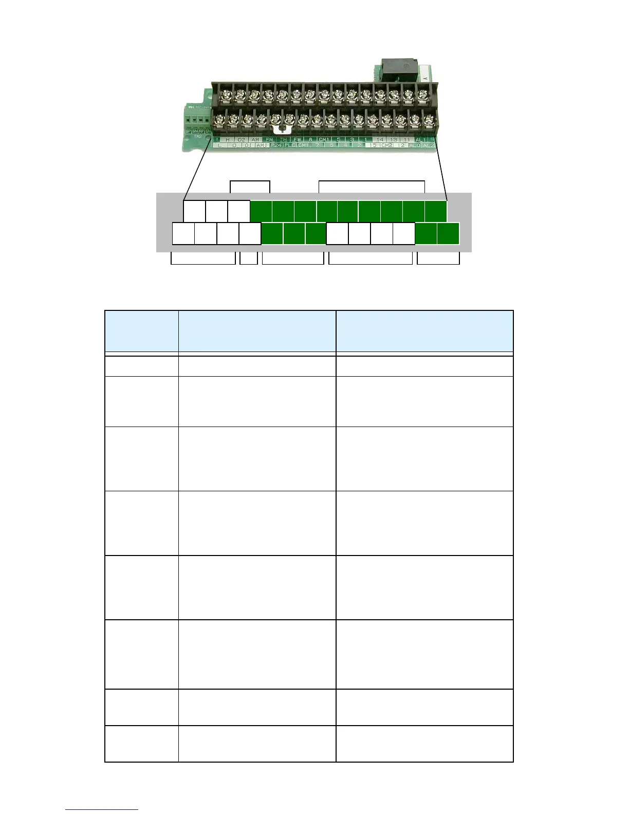
Control Circuit Terminals
Terminal
Name
Description Ratings and Notes
P24 +24V power for inputs 24VDC supply, 100 mA max.
CM1 +24V common Common for 24V supply,
FW, TH, inputs 1 to 5, and
FM. (Note: Do not ground)
PLC Common for logic inputs Common for input terminals
1 to 5, jumper to CM1 for
sinking, jumper to P24 for
sourcing
1, 2, 3, 4, 5 Intelligent (program-
mable) discrete logic
inputs
27VDC max. (use P24 or an
external supply referenced to
terminal CM1), 4.7kΩ input
impedance
FW Forward/stop command 27VDC max. (use P24 or an
external supply referenced to
terminal CM1), 4.7kΩ input
impedance
11C—11A
12C—12A
Intelligent (program-
mable) relay outputs
Normally open contacts
250VAC / 30VDC, 5A (resistive
load) max., 250VAC / 30VDC, 5A
(inductive load) max.
Minimum load 5VDC, 5mA
TH Thermistor input Reference to CM1, min.
thermistor power 100mW
FM PWM output 0 to 10VDC, 1.2 mA max.,
50% duty cycle
L O OI
P24
PLC
CM1
4 2
ALO AL2
AL1
5 3 1
FWFM
AM
AMI
O2
H
TH
Analog inputs
Analog outputs
Power Alarm relay
Logic inputs
Logic outputs
12A 11C 11A12C

 Loading...


