--- 11 ---
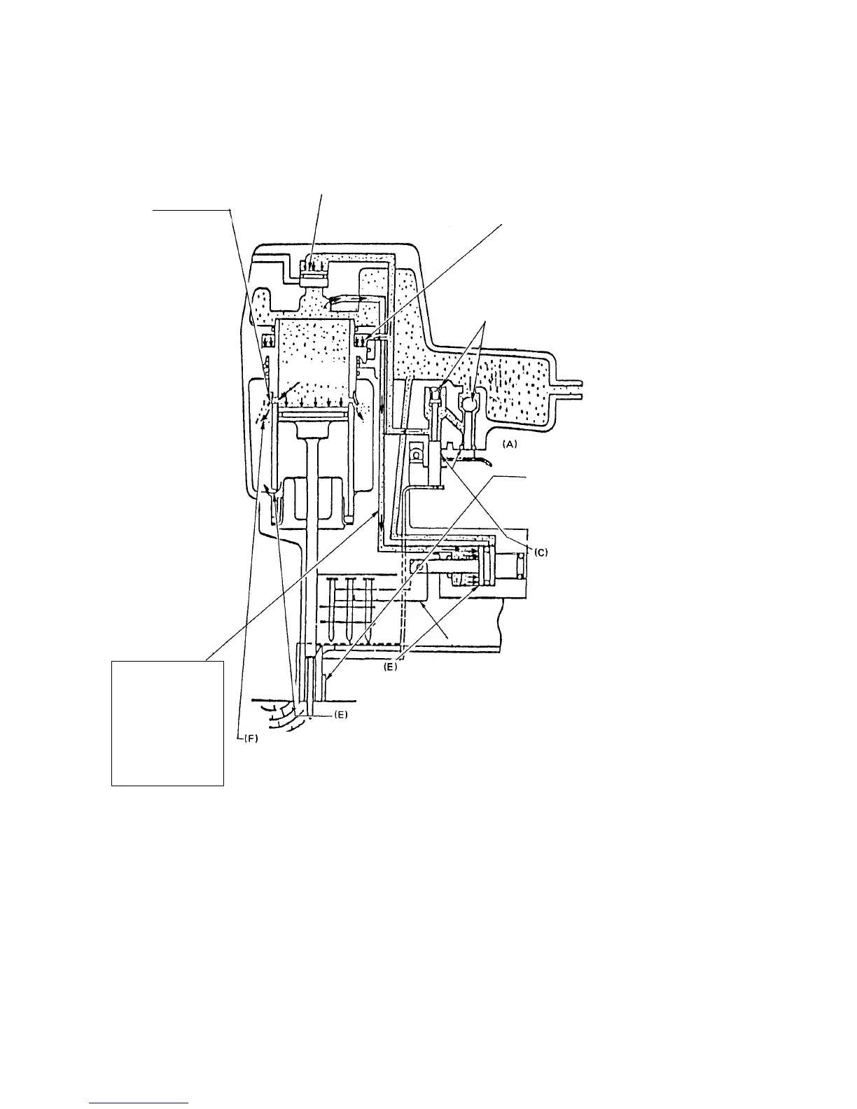
Fig. 5
Although air pressure is applied to both the
upper and lower surfaces of the cylinder, the
cylinder is forced downward due to the larger
effective area of the upper surface.
Accordingly, the upper portion of the cylinder is
opened, and the compressed air forces the
piston downward.
When the trigger and pushing lever are
operated simultaneously, the safety
valve and trigger valve are opened.
When the trigger and pushing
lever are operated
simultaneously, the exhaust
vents are closed.
Compressed air is applied
to the upper side of the
Exhaust Valve [4], forcing it
downward and closing
the Exhaust Vent [5].
As the piston moves downward, the air below the piston
is forced into the Return Air Chamber [6].
When the piston passes the
middle vent, some of the air
pressure passes into the return air
chamber. This supplies auxiliary
air to ensure complete return of
the piston.
Cylinder ring
(2) When the trigger and pushing lever are operated
The trigger and pushing lever are operated
simultaneously.
(Note)
If either the trigger or pushing lever is
operated individually, compressed air will
not enter the valve air passage, and the
nailer will not function.
Because of the larger effective area, the air pressure appied to
the left-side surface of the feed piston overcomes the air pressure
on the right-side, and moves the feed piston to the right.
When the cylinder
moves down,
compressed air
from the head cap
section enters the
passage to the
feed piston.
(D)
(D)
(B)


 To Next Page