--- 33 ---
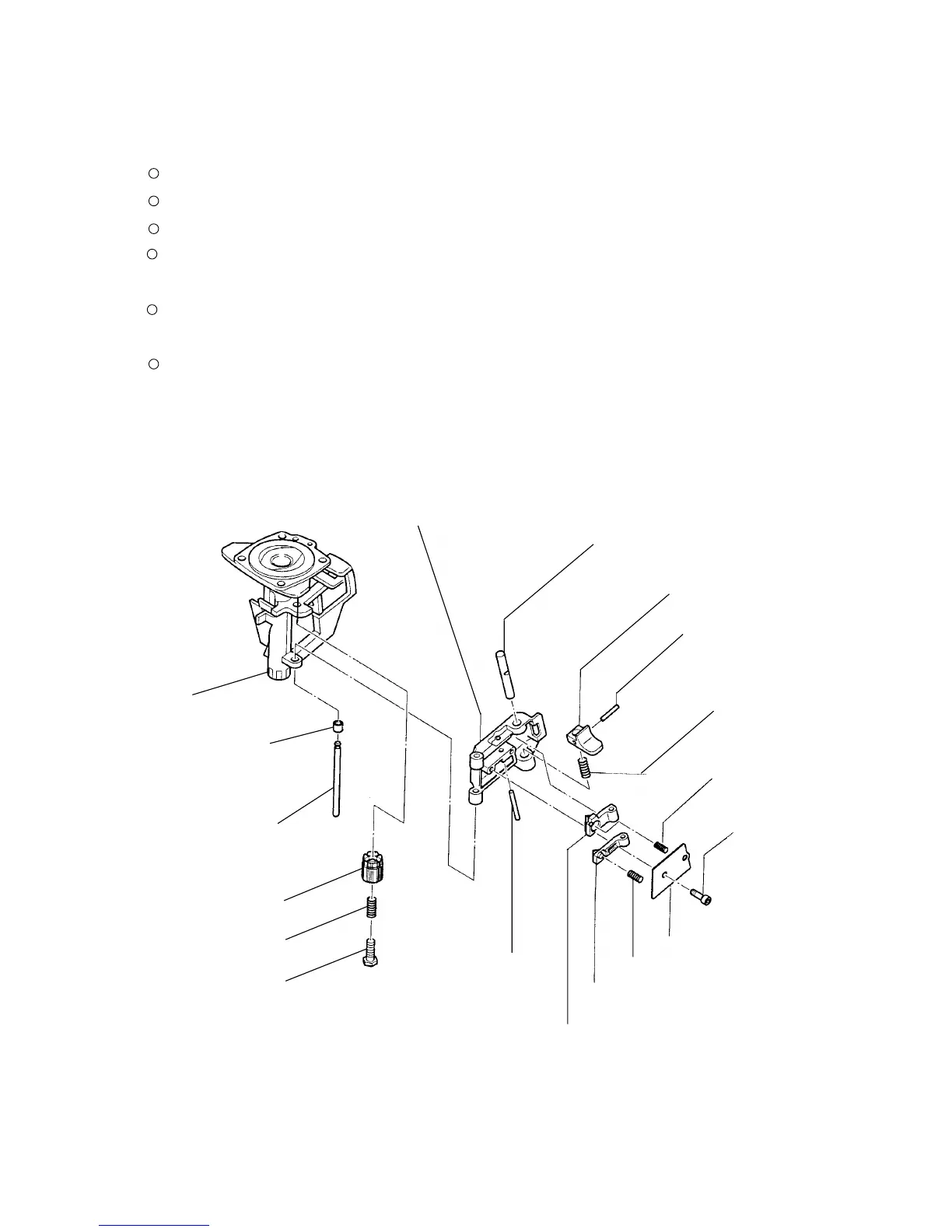
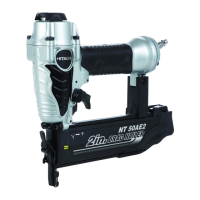
Fig. 18
Shaft Ring [73]
Nose [32]
Guide Lock [80]
Main Stopper Spring [83]
Nail Guide Shaft [74]
Roll Pin D3 x 10 [81]
Nail Guide [78]
Spring [82]
Adjuster [75]
Lock Shaft [79]
Adjuster Spring [76]
10-4. Disassembly and Reassembly of the Driving Section
(1) Nail guide portion and adjuster portion
Tools required
Hex. bar wrench (3 mm, 4 mm)
Phillips screwdriver
Roll pin puller (3 mm (0.118"))
Pliers
(a) Disassembly (See Figs. 18 and 19.)
By following the procedures in paragraph 10-2-1-(a), disassemble the Pushing Lever [38] from the main
body.
Next, pinch the lower tip of the Nail Guide Shaft [74] with pliers and pull down (Fig. 19 (a)). Then the Shaft
Ring [73] can be removed from the Nail Guide Shaft [74] and the Nail Guide Shaft [74] can be pulled out of
the Nose [32]. The entire nail guide section can be removed from the Nose [32]. Do not remove the Nail
Guide Shaft [74] with a flat-blade screwdriver as shown in Fig. 19 (b). Otherwise the Adjuster [75] may be
scratched. Take out the removed Shaft Ring [73] from between the Adjuster [75] and the Nose [32].
Hex. Socket Hd. Bolt
M4 x 6 [84]
Nail Stopper [87]
Nail Guide Cover [89]
Sub Stopper Spring [88]
Roll Pin D3 x 28 [85]
Bolt [77]
Main Nail Stopper [86]