S10 Series SIO Driver
GP-Pro EX Device/PLC Connection Manual
3
1 System Configuration
The system configuration in the case when the External Device of Hitachi, Ltd. and the Display are connected is
shown.
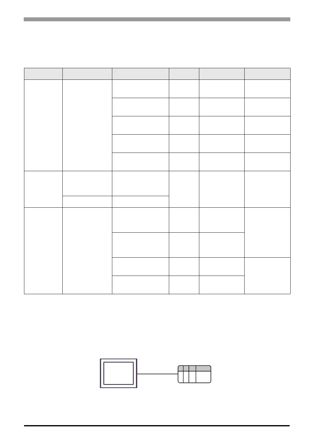
Connection Configuration
• 1:1 connection
Series CPU Link I/F SIO Type Setting Example Cable Diagram
S10V LQP510
*1
*1 To connect to the Display, a C revision or higher version of the LPU Module is required. Check the alphabet on
the right end of the bar code seal (top surface of the LPU Module) for the revision number of the LPU Module.
UP LINK Connector
on LPU Module
RS422/485
(4wire)
Setting Example 1
(page 8)
Cable Diagram 1
(page 23)
LQE560 (CN1) RS232C
Setting Example 2
(page 9)
Cable Diagram 2
(page 29)
LQE560 (CN2) RS232C
Setting Example 3
(page 10)
Cable Diagram 2
(page 29)
LQE565 (CN1)
RS422/485
(4wire)
Setting Example 4
(page 11)
Cable Diagram 1
(page 23)
LQE565 (CN2)
RS422/485
(4wire)
Setting Example 5
(page 12)
Cable Diagram 1
(page 23)
HIDIC-S10α
2α (LWP000)
*2
,
2αE (LWP040)
*2
,
2αH (LWP070)
*2
*2 Connect to the CPU Module's HOST LINK COMPUTER LINK Input/Output Terminal (Upper Calculation I/F).
Terminal Block on
CPU Unit
RS422/485
(4wire)
Setting Example 6
(page 13)
Cable Diagram 3
(page 30)
4α, 4αF LWE805
S10mini
Model S (LQP000),
Model H (LQP010),
Model F (LQP011),
Model D (LQP120),
Model L (LQP800)
LQE060 (CN1)
LQE160 (CN1)
LQE560 (CN1)
RS232C
Setting Example 7
(page 14)
Cable Diagram 2
(page 29)
LQE060 (CN2)
LQE160 (CN2)
LQE560 (CN2)
RS232C
Setting Example 8
(page 15)
LQE165 (CN1)
LQE565 (CN1)
RS422/485
(4wire)
Setting Example 9
(page 16)
Cable Diagram 1
(page 23)
LQE165 (CN2)
LQE565 (CN2)
RS422/485
(4wire)
Setting Example
10 (page 17)
Display
External Device
 Loading...


