Chapter 2 Installation and Wiring
2 - 14
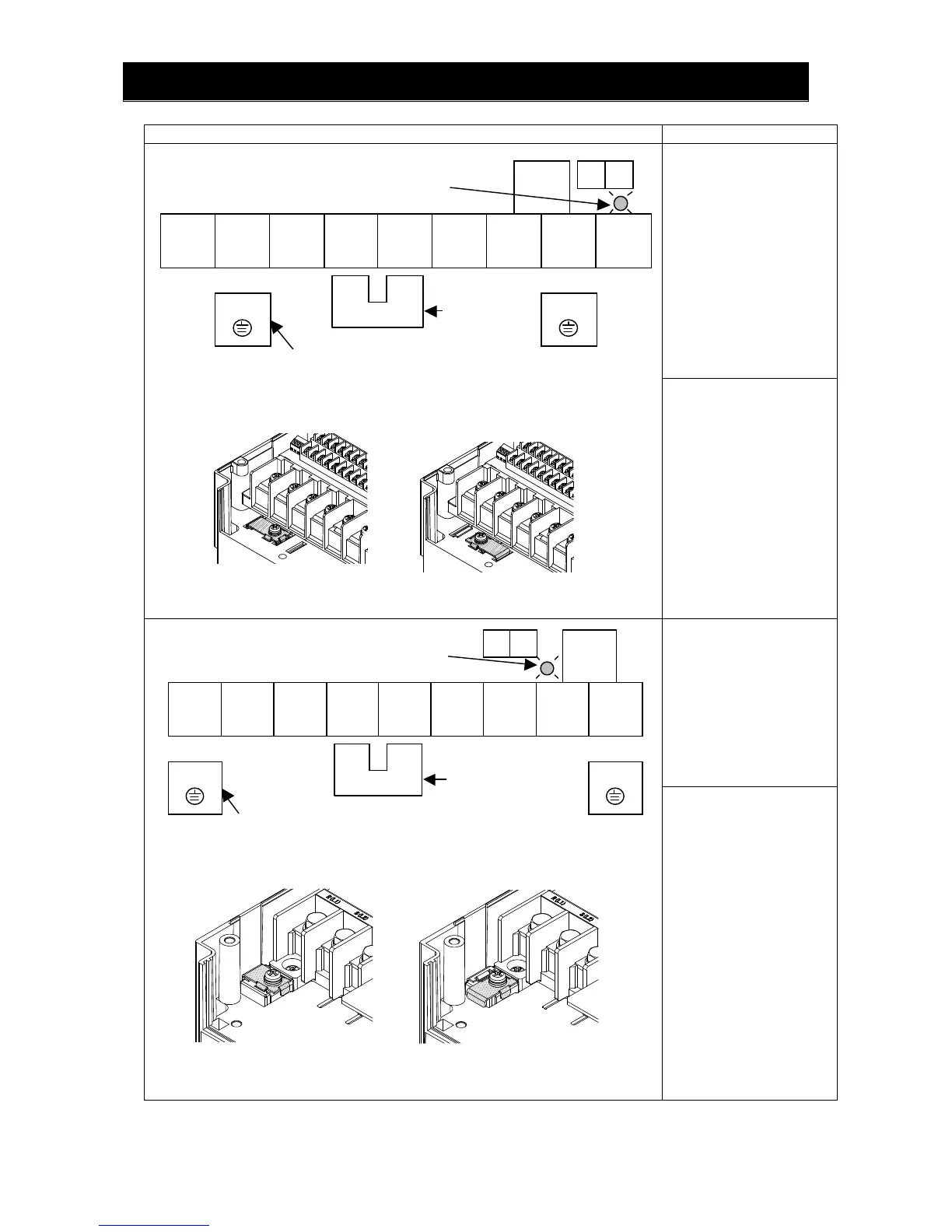
Terminal layout Inverter model
SJ700B-110LFF/LFUF
SJ700B-075,110HFF/HFUF
R0 and T0: M4
Ground terminal: M5
Other terminals: M5
RB
R
(L1)
S
(L2)
T
(L3)
PD
(+1)
P
(+)
N
(-)
U
(T1)
V
(T2)
W
(T3)
R0 T0
チャージランプ
PD-P短絡片
DCLを使用しない場合、
PD-P短絡片を取り外さ
ないでください。
G
EMCフィルタ機能
切り替え用短絡片
(斜線部)付き接地端子
G
SJ700B-150LFF/LFUF
SJ700B-150HFF/HFUF
R0 and T0: M4
Ground terminal: M5
Other terminals: M6
SJ700B-185 to
SJ700B-220LFF/LFUF
SJ700B-185 to
SJ700B-300HFF/HFUF
R0 and T0: M4
Ground terminal: M6
Other terminals: M6
RB
R
(L1)
S
(L2)
T
(L3)
PD
(+1)
P
(+)
N
(-)
U
(T1)
V
(T2)
W
(T3)
R0 T0
G G
SJ700B-300LFF/LFUF
R0 and T0: M4
Ground terminal: M6
Other terminals: M8
Disabling the EMC filter
[Method of enabling/disabling the EMC filter function]
Enabling the EMC filter
(factory setting)
Jumper
connecting
terminals PD
Ground terminal with jumper (shaded in the
figure) to enable/disable the EMC filter function
When not using the DCL,
do not remove the jumper
from terminals PD and P.
Charge lamp
[Method of enabling/disabling the EMC filter function]
Charge lamp
Jumper connecting
terminals PD and P
Ground terminal with
jumper (shaded in the
figure) to enable/disable the
EMC filter function
When not using the DCL,
do not remove the jumper
from terminals PD and P.
Enabling the EMC filter
(factory setting)
Disabling the EMC filter

 Loading...


