48
PMEN0645 rev.0 - 04/2023
6
TERMINALBOARDCONNECTIONS
ELECTRICAL AND CONTROL SETTINGS
◆ Water outlet thermistor for circuit 2 (T
WO2
)
When the installaon is congured with a second circuit the thermistor for the water outlet
temperature have to be connected between terminals 6 and 7 of the terminal board 2.
7
6
T
wo2
Circuit 2
◆ Oponal wireless ON/OFF room thermostat ATW-RTU-04
The heat pump system has been designed to allow the connecon of a remote ON/OFF thermostat
to eecvely control the home temperature. Depending on the room temperature, the thermostat
will turn the system to ON or OFF.
a. If no thermostat is installed
Terminals 13 and 14 are jumped if there is no ON/OFF receiver connected. When no remote
thermostat is installed the operang condion for the unit (Thermo ON/OFF) will be
controlled by the water calculaon control system.
13 14
Jumper
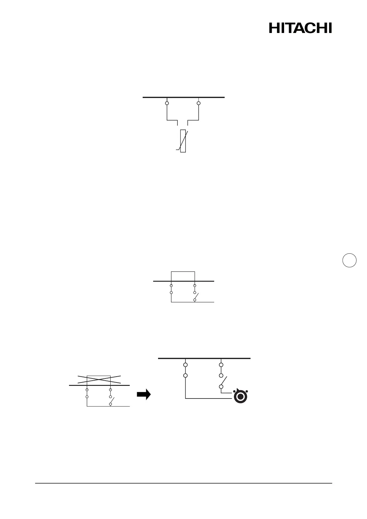
b. Installaon of the ATW‑RTU‑04
In case of seng an installaon with 2 circuits (circuit 1 and circuit 2) and the same demand
ON/OFF is used for both of them, remove the jumper between terminals 13 and 14 of the
Terminal board 2 and connect the RF receiver as shown in the following picture.
Thermostat requirements:
• Power supply: 230V AC
• Contact voltage: 230V
13 14
13 14
Jumper
Common
Line
Demand ON/OFF
Receiver input 2
 Loading...