E1 Series Servo Drive EtherCAT(CoE) Communications Command Manual Object Dictionary
3-44 HIWIN MIKROSYSTEM Corp.
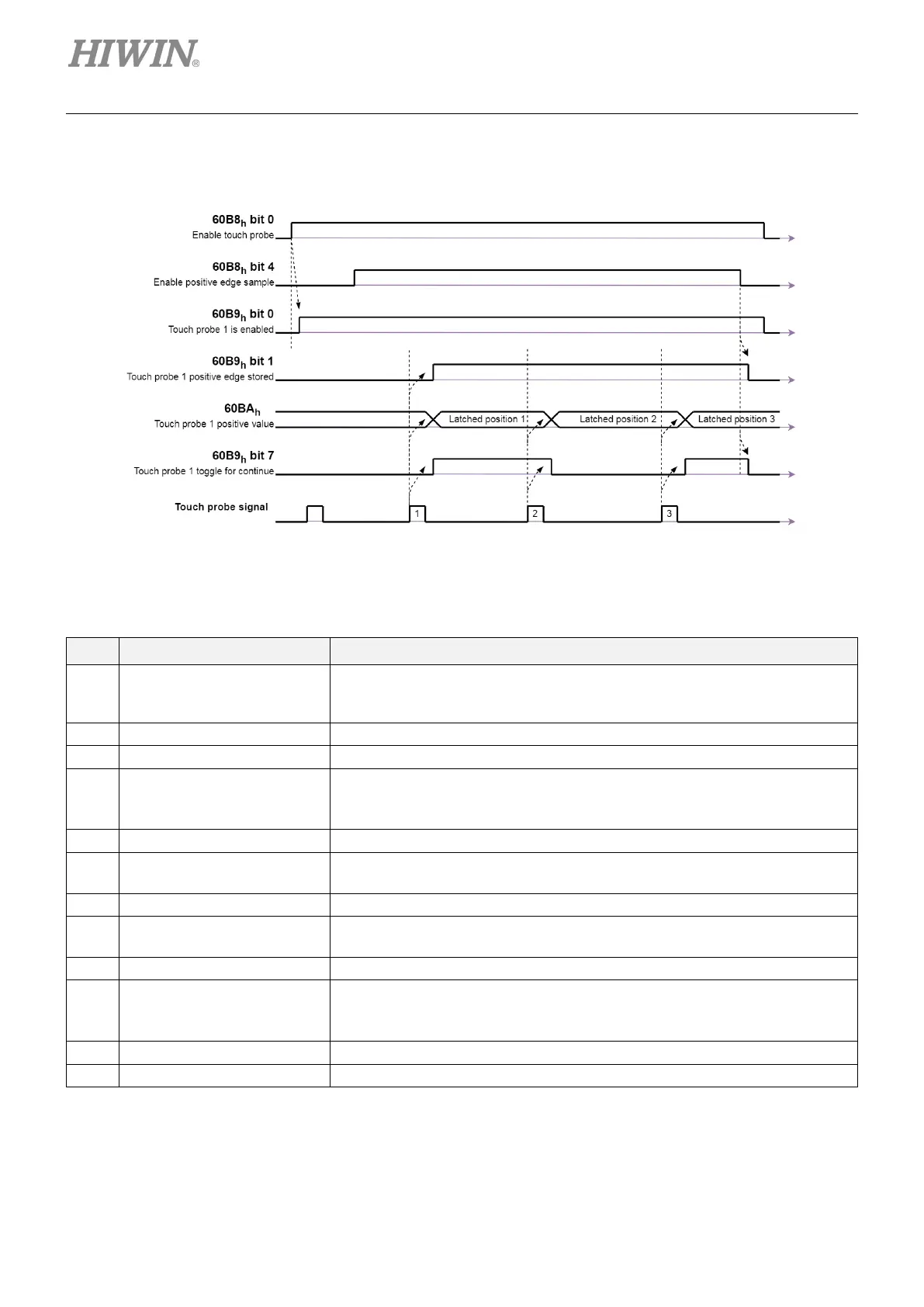
Example of touch probe 1 continuous mode
Figure 3.2.9.2
Table 3.2.9.3
# Value Description
(1)
60B8h bit 0 = 1
60B8h bit 1 = 1
Enable touch probe 1.
Continuous state.
Configure and enable touch probe 1 positive edge.
→
Status “Touch probe 1 enables” is set.
There is a positive edge in external touch probe signal.
(4)
→
→ 60B9h bit 7 = 1
→
Status “Touch probe 1 positve edge stored” is set.
Touch probe 1 positve edge is updated.
Touch probe position 1 positive value is stored.
There is a positive edge in external touch probe signal.
(6)
→
→
Touch probe 1 positve edge is updated.
Touch probe position 1 positive value is stored.
(7) There is a positive edge in external touch probe signal.
(8)
→
→
Touch probe 1 positve edge is updated.
Touch probe position 1 positive value is stored.
Positive edge sample is disabled.
(10)
→
→ 60B9h bit 7 = 0
→
Status “Touch probe 1 positve edge stored” is reset.
Continuous latch status is reset.
Touch probe position 1 positive value is not changed.
→
Touch probe 1 is disabled.
→
 Loading...


