HQ Series Quarter-turn Electric Actuator
Installation Operation& Maintenance Manual
Doc No. : HumG-HQ-21 Rev2 Page 15 / 26 Valve Automation Leader, HKC
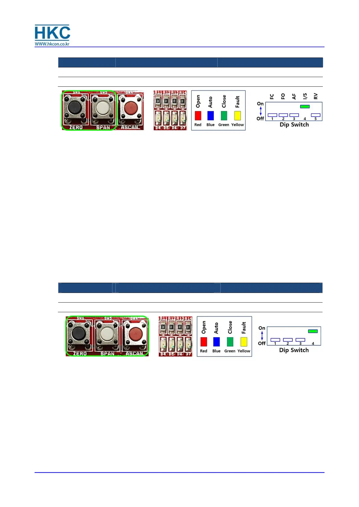
4.9.11. Random command signal setting
Dip Switch PCU model Power source
SW3 PCU-EB-V1.5D for AC
SW1 PCU-DC-V2.1C for DC
① This function is intended to change the Zero (fully close) and Span (Fully open) signal.
② Adjustable setting range of the Zero signal : about 3~8mA dc
③ Adjustable setting range of the Span signal : about 16~21mA dc
※ Example: Set 5 mA dc as Zero and 19 mA dc as Span signal
Turn up No. 4 switch (I/S input set) of the dip switch.
Both Red and Green LED will be flickering quickly.
About 1.5 seconds later, only the Green LED will be flickering.
Input 5mA to command signal on the input terminal and then press the ZERO (black) button
to unlock.
If the setting is successfully done, Yellow LED will flicker once and Green LED will be ON
(setting completed). Then, Red LED will be flickering for input setting.
Input 19mA to command signal on the input terminal and then press the SPAN (white)
button to unlock.
If the setting is successfully done, Yellow LED will flicker once and Red LED will be ON
(setting completed).
Wait until only the Green LED flickers after both Red and Green LED flicker for about 1.5
second.
Turn down No. 4 of the dip switch (I/S input set) to finish the setting.
※ If No. 4 switch of the dip switch is turned down during setting, the setting will be cancelled.
※ If there is no input for 2 minutes, the setting process will also be cancelled.
4.9.12. Adjust output (feedback) signal
Dip Switch PCU model Power source
SW7 PCU-EB-V1.5D for AC
SW2 PCU-DC-V2.1C for DC
① Adjust Zero (4mA) and Span (20mA) value of the output signal.
② Each time the zero button (Black) is pressed, the output signal will be decreased.
③ Each time the span button (White) is pressed, the output signal will be increased.
※ Example: Set 4 mA dc as Zero and 20 mA dc as Span signal.
Turn up No. 4 switch of the dip switch.
Wait until only the Green LED flickers after both Red and Green LED flicker for about 1.5
second.
Adjust output signal value to 4 mA by pushing the Zero or Span button.
After checking the 4 mA output signal, press ASCAN button (Red).
Yellow LED will be ON and OFF.
Confirm the Green LED is ON and Red LED is flickering.
Adjust the output signal value to 20 mA by pushing the Zero or Span button.
After checking the 20 mA output signal, press ASCAN button (Red).
Yellow LED will be ON and OFF.
Confirm the Red LED is ON.

 Loading...