HQ Series Quarter-turn Electric Actuator
Installation Operation& Maintenance Manual
Doc No. : HumG-HQ-21 Rev2 Page 16 / 26 Valve Automation Leader, HKC
Wait until only the Green LED flickers after both Red and Green LED flicker for about 1.5
second.
Turn down No. 4 switch of the dip switch.
※ If No. 4 switch of the dip switch is turned down during the setting process, the setting will be
cancelled.
※ If there is no input for 2 minutes, the setting process will also be cancelled.
4.9.13. Manual operation mode
① This function allows the user to manually operate the actuator.
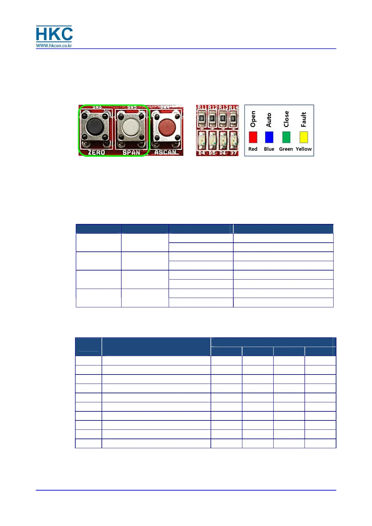
② To access this function, press ZERO (Black) and SPAN (White) buttons simultaneously for 1 second.
Then, yellow LED will be ON to indicate that the actuator is in Manual Operation mode.
③ Pressing the ZERO button will move the actuator to close position and pressing the SPAN button
will move the actuator to open position.
④ If user do not operates within 10 seconds or press ZERO and SPAN buttons again simultaneously
for 1 second, PCU board will automatically terminate the Manual Operation mode.
4.9.14. LED display
① Operating display
Status LED Color Display Function
Open Red
On Fully opened
Flicker Moving to open position
Auto Blue
On Power on
Flicker Auto setting
Close Green
On Fully closed
Flicker Moving to close position
Fault Yellow
On Manual mode
Flicker Malfunction
② Error display on the PCU-EB-V1.5D board for AC
PCU-EB-V1.5D board for AC indicates an error condition when the yellow LED is flickering.
At this time, when user presses the ZERO (Black button), user can get the error type from LED status
as below.
No
Error type
(Malfunction)
LED display
Red Blue Green Yellow
1 EEPROM error Off Off Off On
2 Input signal initialization error Off Off On Off
3 Auto setting initialization error Off Off On On
4 Input signal error Off On Off Off
5 Reverse turn the motor Off On Off On
6 Command signal selector switch error Off On On Off
7 Abnormal of potentiometer Off On On On
8 Open position error On Off Off Off
9 Close position error On Off Off On
10 Limit switch error On Off On Off
③ Error display on the PCU-DC-V2.1C board for DC
PCU-DC-V2.1C board for DC also indicates an error condition when the yellow LED is flickering. At
this time, when user push the ZERO (Black button), user can get the error type from LED status as
below.

 Loading...