How to configure an Anybus AS-Interface Master module
SCM-7032-036
Rev 1.02
5.3 Memory Mapping
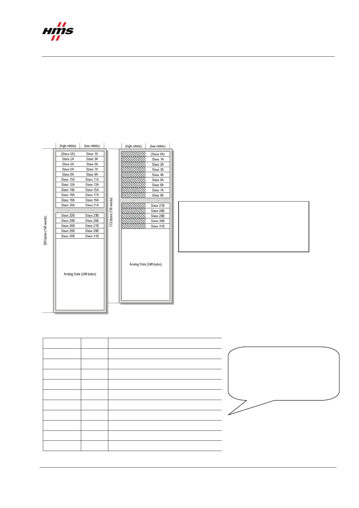
The figure below shows the memory mapping of the AS-Interface Master generally.
Note: For the X-gateway the memory mapping will be different depending on if the Control Word, Status
Word and Live List are used. This info will be mapped before the digital I/O data, please see the X-gateway
Interface Addendum for details. The mapping is performed in the same way for both input and output data of
the X-gateway.
Nibble mode Byte mode
The figure to the left shows the memory
mapping of the AS-Interface Master. The
analogue data will always be mapped after
the digital data.
Figure 13 The memory mapping using the auto configuration.
The mapping of the analogue data is shown in the figure below.
Offset (byte) Word no.
Description
0... 1 1 Analogue Input Data for slave 1, channel 0
2... 3 2 Analogue Input Data for slave 1, channel 1
4... 5 3 Analogue Input Data for slave 1, channel 2
6... 7 4 Analogue Input Data for slave 1, channel 3
8... 9 5 Analogue Input Data for slave 2, channel 0
10... 11 6 Analogue Input Data for slave 2, channel 1
12... 13 7 Analogue Input Data for slave 2B, channel 0
14... 15 8 Analogue Input Data for slave 2B, channel 1
... ..
246... 247 124 Analogue Input Data for slave 31, channel 3
When extended addressing is used,
for example slaves 2 and 2B,
the analogue data area is shared.
In other words slave 2 and 2B will
use 4 b
tes of analo
ue data each.
Figure 14 The mapping of the analogue I/O data.
www.anybus.com HMS Industrial Networks AB
Page 14 (19)