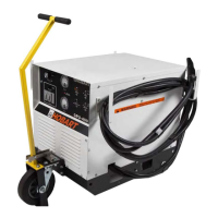
Normally, a visual inspection will not find a transformer problem until the failure is very severe. The
typical inspection is a voltage measurement test for rated primary input voltage and for 6 rated and
balanced line to neutral AC voltages at the transformer secondary terminals. Refer to the applicable
voltage changeover diagram for the input voltage test points and to the applicable connection dia-
gram for the transformer secondary test connection points. The normal transformer line to neutral sec-
ondary voltage is approximately 33 V AC with no output amperage. Line to line voltage on the
secondary is 66 V. If the fuses blow or circuit breakers trip immediately in the user-supplied discon-
nect switch and no evidence of lead shorting exists at the input contactor, or the primary connection
terminal board, both the main transformer and the SCR control assembly are suspect. Open the input
disconnect switch external to the power supply, label all the transformer leads going to the six U-
shaped SCR heat sinks before disconnecting and insulating the leads. Also disconnect the flyback di-
ode “pigtail” lead 105 and L1 filter lead 104. These connection changes enables you to check the
transformer only.
After verifying that input power can be turned on from the power source safely, turn the rated input
power on. After the S1 input contactor switch is closed carefully measure the output line to neutral
voltages if the primary input is still on. If the input power source voltage trips out when the unit is
turned on, the main transformer has probably failed. To verify failure, disconnect the input power at
the power source and then remove the copper links
(jumpers)
on the main voltage changeover board.
If turning the primary input voltage on, after input breakers at the power source have been reset, re-
sults in no high input current, the main transformer is bad.
If the problem still exists, the problem is not in the main transformer. Check the main connection termi-
nal board for faulty connections and check the control transformer and input contactor. Go to 4.B if no
problem existed with all the SCR devices disconnected.
B. Silicon Controlled Rectifier Assembly and Flyback Diode
(1) Visual
No visual failure capability is possible with the SCR assembly, except for faulty leads or miscon-
nections which we assume have been found and corrected. The input power at the power source
should be turned off at the start of the SCR check out.
(2) Voltohmmeter
To check with voltohmmeter, set the meter to the RX1 scale and check for a shorted SCR by
measuring between each of the 6 U-shaped heat sink and the main heat sink. No reading should
be possible with either polarity of lead connection. The flyback diode should read 4 to 14 ohms in
one direction and a very high reading with the leads from the voltohmmeter reversed. If the fly-
back diode is shorted,
(a rare occurrence)
replace it with the same type of device
(see Chapter 4 -
Replacement Parts)
taking care to torque the nut to the stud with 4.2 to 5.2 foot. pounds
(5.7 to
7.05 newton meters).
If the SCR bridge has one or more SCR devices showing a short circuit or
low ohmmeter reading, it is recommended that the GPU-600 power supply be sent to the factory
or an authorized repair station for repair. A replacement SCR bridge subassembly can be ob-
tained from the factory which would allow the customer to replace the faulty SCR bridge assem-
bly without special tools and techniques. He must still be careful to exactly replace all the
mounted subassemblies and the connection leads exactly as they were on the faulty heat sink as-
sembly. Special tools, parts, and techniques are required to replace single SCR devices on the
heat sink assembly.
If the SCR heat sink and diode assembly checks good with the voltohmmeter, the components
could still be failing due to voltage breakdown at voltages above that of the voltohmmeter. Go to
4. B.
(3)
Voltage test.
OM-2010
April 10/89 Revised 3-2
Page 5

 Loading...