CHAPTER 2. DESCRIPTION AND
OPERATION
SECTION 1. DESCRIPTION
1. General
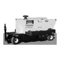
This manual describes a portable,
(see Fig. 1)
Solid State controlled, transformer-rectifier DC power sup-
ply rated at a continuous output of 28-V, 600-A DC to an aircraft load or a battery load. The rated input
voltages, currents, and frequency along with weights and dimensions are given in the Specifications and
Capabilities Table in Figure 2. This book will generally refer to this equipment as a GPU-600 power sup-
ply or power supply. See Figure 1 for a descriptive drawing showing the major components or sub-assem-
blies generally present in the design. A detailed description of each design variation is given later.
The power supplies are usually identical or nearly so in appearance. The specification numbers relate to
different rated input power requirements, possible output rating changes, or limited component specifica-
tion changes. The specification number consists of the number S
(for specification)
6683 or 6883A with a
dash number added for each specification change, i.e., S6683-1 or 6883A-1 is the first design specifica-
tion made in the series.
The phase angle control method for obtaining the DC output voltage is the use of silicon controlled rectifi-
ers to select the desired portion of the voltage that has been stepped down by the main transformer to pro-
duce the DC voltage. As shown in Figure 1, the power supply consists of:
A. A punched and formed steel base
(1, Fig. 1)
with 10 inch
(254 mm)
diameter wheels
(2)
near the
rear and steerable castor wheels
(3)
at the front.
B. A formed and louvered steel front panel
(4)
for mounting most of the accessible controls and me-
ters.
C. A formed and louvered sheet steel rear panel
(5, Fig. 1)
to which the fan assembly
(18, 19, Fig. 3)
and the SCR assembly
(17, Fig. 3)
are mounted inside the power supply.
D. A sheet steel top panel
(7, Fig. 1 and 15, Fig. 3)
removable for access to the input fuses, main in-
put terminal board
(16, Fig. 3),
snubber board
(1, Fig. 5)
and control transformer connections when
the input power is off.
E. A sheet steel left side panel
(11, Fig. 3),
to which two cable hangers are mounted. A door in this
panel permits output cable connections.
F. A sheet steel right side panel
(8, Fig. 1)
with access doors to the solid state control printed circuit
board
(9, Fig. 1)
and to the fuse block on the silicon controlled rectifier assembly
(10, Fig. 1)
. Two ca-
ble hangers also mount to this panel.
G. A steel vertical lifting yoke
(3, Fig. 3)
with baffle assembly attached to the base between the front
and rear panels.
OM-2010
April 10/89 Revised 2-1
Page 1