A3SuperUserManualVer.2.6
HTTP://WWW.HOBBYEAGLE.COM Feb.20,2014
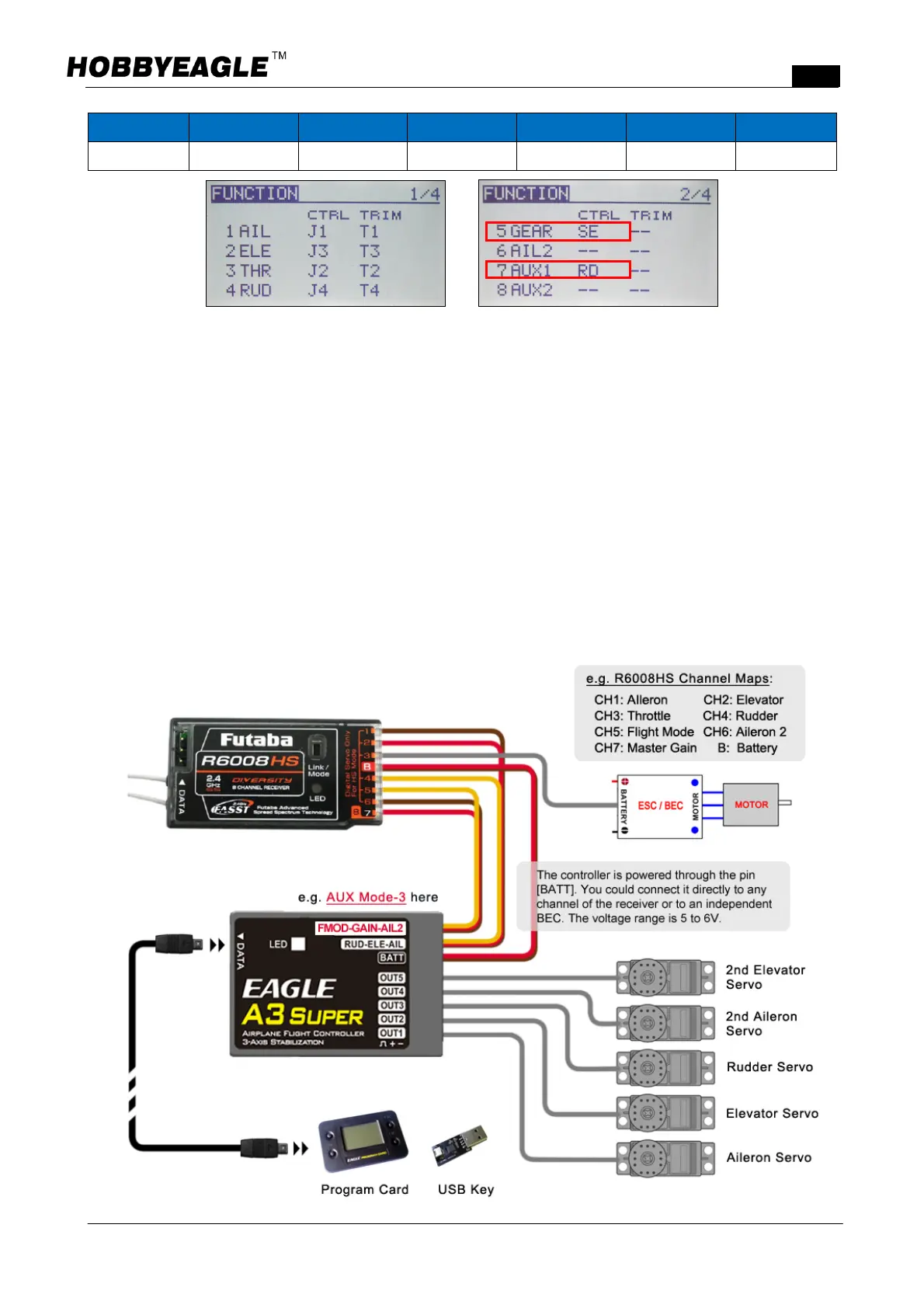
CH1 CH2 CH3 CH4 CH5 CH6 CH7
Aileron Elevator Throttle Rudder FlightMode Aileron2 MasterGain
A 3positionswitch(SE)isassignedtochannel5forflightmodeswitching,whichisimplementedbyusingthe
GEAR functionintheradio system. A knob (RD) is assigned tochannel7 for theadjustment of master gain,
surelyyoumightusea3positionswitchinsteadtogeta3levelgaincontrolifyoulike.
6.4.Wiring
Connectalltherequiredchannelsbetweenthecontrollerandthereceiver,usingtheincludedplain3wirecables,
which have only onelead ofthe controlsignal onthe receiverside,andare connectedtothecontroller onthe
combinedconnector.Thecontrollerrequiresatleast3receiverchannels,upto7channels.ThechannelsofAIL,
ELEandRUDmustbeconnectedallthetimeotherwisethecontrollerwillnotwork.Theother3pinsshouldbe
connectedaccordingtotheAUXmodecurrentlyselected.ThethrottleservoorESCisconnectedasnormaltothe
throttlechannelofthereceiverwithoutbridgingthecontroller. Theillustrationbelowshowsthewiringmethod
onlyforAUXMode3,whichisusedinthiscase.