A3SuperUserManualVer.2.6
HTTP://WWW.HOBBYEAGLE.COM Feb.20,2014
6.5.PowerSupply
Thecontrollerispoweredthroughthe[BATT]pins.Toachieveit,youcanconnectitdirectlytoanyidlechannel
ofthereceiverusingtheincluded3wirereceivercable,ortoanindependentBEC.Thevoltagerangeis5to6V.If
aBECisusedasthepowersupply,pleasemakesurethatthevoltagenotexceedingtheworkingvoltagepermitof
your servos, and verify that the BEC havesufficient capacity to provide working current for all the electronic
devicesontheplaneespeciallywhenusingseveralhightorqueservos.
6.6.FlightModeChannel(FMOD)
[FMOD]isusedforswitchingtheflightmode.Wehaveassigneda3positionswitchtoitas mentionedabove.
Theexpectedflightmodecanbepresetinthefunction"FlightMode"oftheprogramcardorconfigtool.System
will default to the mode which assigned to position1 if you leave this pin unconnected. Even so, it is
recommendedthat youalways usean
independent channel to switch the
modeinflight.
6.7.MasterGainControlChannel(GAIN)
[GAIN]isusedtocontrolthemastergainremotely.Inthiscase,weuseaknob(RD)tomakealinearadjustment
of the gain. Surely a3position switch can be used instead to get a 3level gain control.. Once connected, the
master gain will be controlled by the transmitter directly. Only when the pin is disabled or unconnected, the
mastergaincanbemodifiedviatheprogramcardorconfigtool.
6.8.DualAileron&DualElevator
AtruedualaileronandelevatorsystemisavailablenowonA3Super,theOUT4isforthe2ndaileronservoand
the OUT5 is for the 2nd elevator servo. Mostly we use two aileron servos with single aileron input, in this
condition,youjustneedtoplugthetwoaileronservosintoOUT1andOUT4respectively.TheOUT4willbecome
a mirrorofOUT1bythesoftwareautomatically,whichcanavoidthehassleusingaYextensioncable. Thisis
verysimilarinconnectingthedualelevator.
The dual channelssharethesamesettings,suchas servolimits, gyrodirectionandgain settingandso on.For
example,ifyousettheservolimitsofaileronchannelto ±80%,themaximumtravelofbothaileronservoswill
be ±80%.
Usuallythe2servosshouldbeinstalledsymmetricallyonthebothsideofthewing,butyoucanmakethem
inanoppositedirectionifyoulike.TheseparategyroreversingforAIL2andELE2willhelpyougetthe
correctresult.
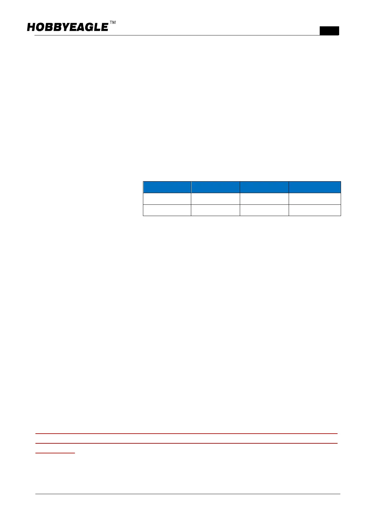
Position1 Position2 Position3
PulseWidth
10201320μs 1320~1720μs 17202020μs
Default
NormalMode 3DMode Selfbalance