Operation the Chop- and Mitre Saw
KGZ Series | Version 2.02 | EN 19
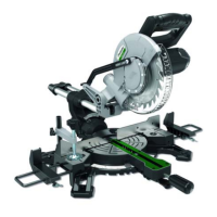
8.1.4Rotating Lower Blade Guard (Model KGZ
210 E)
The rotating lower blade guard (Pos. 6) provides protec-
tion from both sides of the blade. It retracts over the up-
per blade guard (Pos. 4) as the saw is lowered into the
workpiece.
8.1.5 Turning ON and OFF (Model KGZ 210 E)
Step 1: To turn on the saw, slide the switch lock (28) to
the left and press the on / off switch (17).
Step 2: To turn off the saw, release the ON / OFF switch
(17).
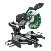
8.1.6Adjusting the squareness of the saw
blade to the table on model KGZ 210 E
Step 1: Make sure the power plug is disconnected from
the power outlet.
Step 2: Push the release latch (28) towards the handle.
Slide the saw arm (1) to the lowest position and
press the release button (2) to hold the saw arm
in the transport position.
Step 3: Loosen the miter locks (18) and raise the miter
lock (19).
Step 4: Turn the table (14) until the pointer is at 0 °.
Step 5: Release the miter lock (19) and tighten the miter
locks (20).
Step 6: Loosen the miter lock (10) and set the saw arm
(1) to 0 ° miter (the saw blade 90 ° to the miter
table). Tighten the tilt lock (10).
Step 7: Place a combination square against the table
(14) and the flat part of the saw blade.
Step 8: Turn the saw blade by hand and check the align-
ment of the saw blade with the table in several
places.
Step 9: The edge of the square and the saw blade
should be parallel. If the saw blade deviates
from the set angle, adjust as follows:
Step 10: Use a 10 mm wrench or an adjustable wrench
to loosen the locking nut that secures the 0 °
angle adjustment screw (27).
Step 11: Release the tilt lock (10).
Step 12: Adjust the 0 ° Bevel Adjustment Screw (27) with
a 4mm Allen Wrench to align the saw blade with
the Combi Wheel.
Step 13: Loosen the Phillips head screw that holds the
tilt scale pointer (11) and adjust the pointer posi-
tion to exactly zero on the scale. Tighten the
screw again.
Step 14: Retighten the Tilt Lock (10) and the lock nut that
secures the 0 ° Tilt Adjustment Screw (27).
8.1.7Adjusting the squareness of the stop to
the table in the model KGZ 210 E
Step 1: Make sure the power plug is disconnected from
the power outlet.
Step 2: Push the release latch (28) towards the handle.
Slide the saw arm (1) to the lowest position and
press the release button (2) to hold the saw arm
in the transport position.
Step 3: Loosen the miter locks (18) and raise the miter
lock (19).
Step 4: Turn the table (14) until the pointer is at 0 °.
Step 5: Release the miter lock (19) and tighten the miter
locks (18).
Step 6: Use a 5 mm Allen wrench and loosen the two
screws securing the stopper (12) to the base
frame.
Step 7: Place a combination square against the stop (12)
and along the saw blade.
Step 8: Adjust the fence so that it is perpendicular to the
saw blade.
Step 9: Tighten the screws securing the stopper (12).
Step 10: Loosen the Phillips screw that holds the gauge
of the Gauge Angle Indicator (15) and set it to
accurately indicate the zero point of the bevel
angle scale.
Step 11: Tighten the miter angle indicator locking screw.
8.1.8Cross Cut (Model KGZ 210 E)
A crosscut is made by cutting across the grain of the
workpiece. A 90° crosscut is made with the mitre table
set at 0°. Mitre crosscuts are made with the table set at
some angle other than zero.
ATTENTION!
If possible, always use a clamping device such as a
‘G" clamp to secure your workpiece.
When cutting your workpiece, keep your hands well
away from the blade area.
Do not remove a cut-off piece on the right-hand side
of the blade using your left hand.