BF40A-BFSOA
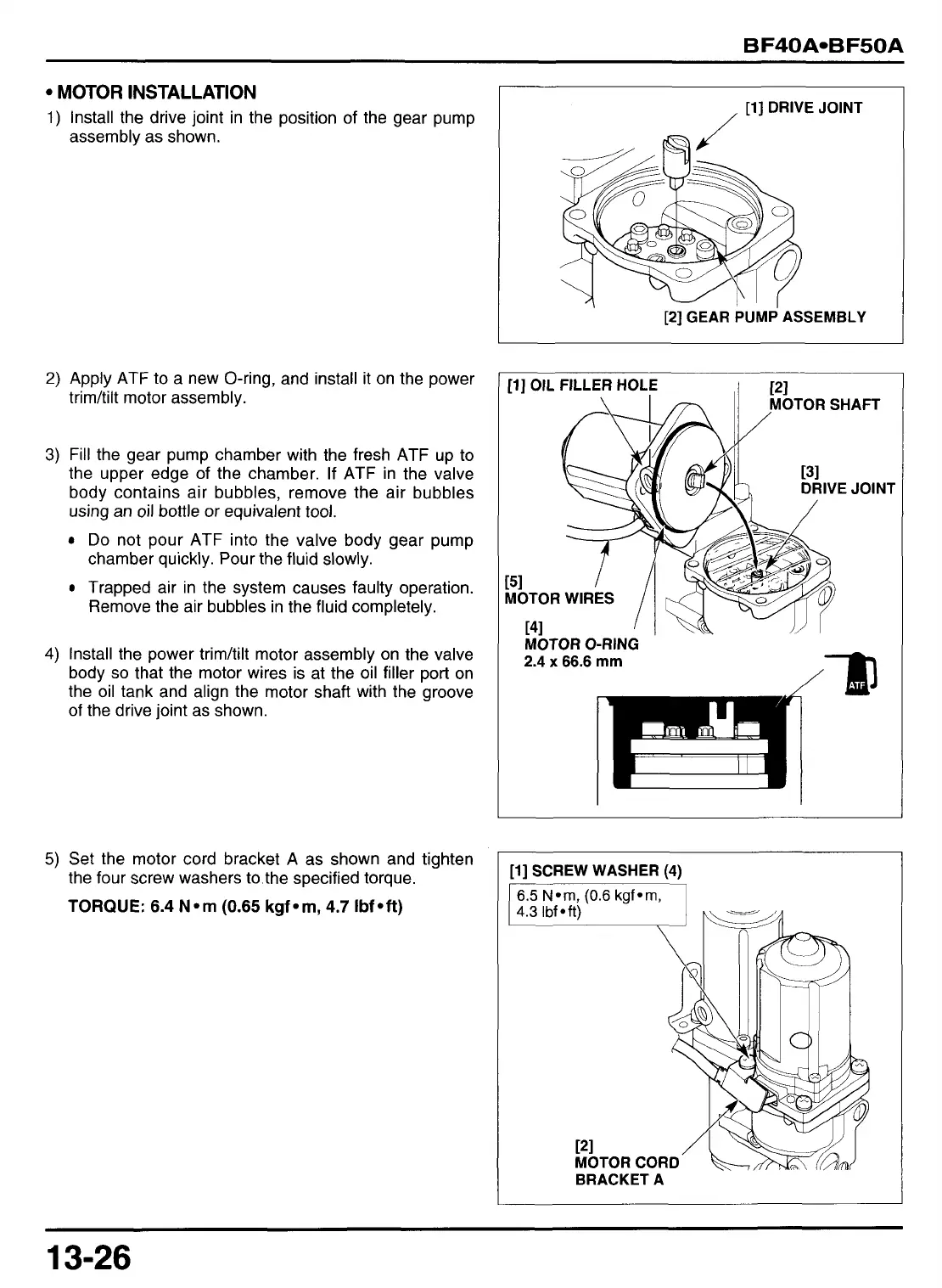
MOTOR
INSTALLATION
1)
Install the drive joint in the position of the gear pump
assembly as shown.
2)
Apply ATF to a new O-ring, and install it on the power
trimhilt motor assembly.
3)
Fill the gear pump chamber with the fresh
ATF
up
to
the upper edge of the chamber.
If
ATF
in the valve
body contains air bubbles, remove the air bubbles
using an oil bottle or equivalent
tool.
Do
not pour ATF into the valve body gear pump
chamber quickly. Pour the fluid slowly.
Trapped air in the system causes faulty operation.
Remove the air bubbles in the fluid completely.
4)
Install the power trimhlt motor assembly on the valve
body
so
that the motor wires is at the oil filler port on
the oil tank and align the motor shaft with the groove
of the drive joint as shown.
5)
Set the motor cord bracket A as shown and tighten
the four screw washers
to
the specified torque.
TORQUE:
6.4
Norn
(0.65
kgfom,
4.7
Ibfoft)
[l
]
DRIVE
JOINT
/
I
[2] GEAR
PUMP
ASSEMBLY
[l
]
OIL
FILLER HOLE
,I
PI
MOTOR O-RING
2.4x66.6
mm
[l]
SCREW WASHER (4)
MOTOR CORD
BRACKET A
13-26